
- Calculation function operates on spindle displacement.
- Entering the appropriate formula factors for a fixture dedicated to the application enables direct measurement readout, thereby eliminating any need for the conversion tables previously needed for those applications where fixtures are typically used.
- Peak-Value Run-out/MAX/MIN Hold enables GO/±NG judgement for peak value.
- Simple operation of many functions with five buttons and status icons.
- Wide LCD and new analog bar graph are now standard on all models.
- Sampling can be performed fifty times per second for accurate detection of maximum, minimum and run-out values.
SPECIFICATIONS
Metric
| Order No.* | Range | Resolution (selectable) | Accuracy*1 | Hysteresis*1 | Repeatability*1 | Measuring force | Power supply | Battery life (normal use)*2 | Net weight |
|---|---|---|---|---|---|---|---|---|---|
| 543-340B | 12.7mm | 12 steps*5 | 0.003mm | 0.002 mm | 0.002 mm | 1.5N or less | CR2032 x 1 pc. | Approx. 1 year | 170 g |
| 543-590B | 25.4mm | 1.8N or less*3 | 190 g | ||||||
| 543-595B | 50.8mm | 0.006mm | 2.3N or less*3 | 260 g |
* Flat back only
Inch/Metric
| Order No.* | Resolution (selectable) | Range | Accuracy*1 | Hysteresis*1 | Repeatability*1 | Measuring force | Power supply | Battery life (normal use)*2 | Net weight |
|---|---|---|---|---|---|---|---|---|---|
| 543-341B |
12 steps*5 |
.5″/12.7mm |
±.00010″ / 0.003 mm |
.00010″ / 0.002 mm |
00010″ / 0.002 mm |
1.5N or less |
CR2032 x 1 pc. |
Approx. 1 year |
170 g |
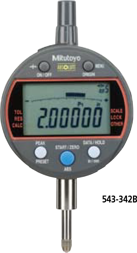
| 543-342B | |||||||||
| 543-591B | 1”/25.4mm | 1.8N or less*3 | 190 g | ||||||
| 543-592B | |||||||||
| 543-596B | 2”/50.8mm | ±.00025″ / 0.006 mm | 2.3N or less*3 | 260 g | |||||
| 543-597B |
* Flat back only
Note: All instruments in this series are of the flat back type.
The back is interchangeable with the standard backs for Series 2.
Refer to page F-55 for details of the optional backs.
*1 Does not include quantizing error (±1 count). Valid for resolution set to 0.001mm/’.00005″ and coefficients A=1, B=0 and C=0.
*2 Applies only if not connected to a data processor. Battery life depends on use of the indicator. Use the above value as a guide
only. (TIP) Battery life with Peak detection mode and FAST mode ON is about 10 months.
*3 Applies for a spindle orientation between the spindle pointing vertically downward to the spindle horizontal.
*4 The resolution can be selected from one of 12 steps (Refer to table right).
DIMENSIONS
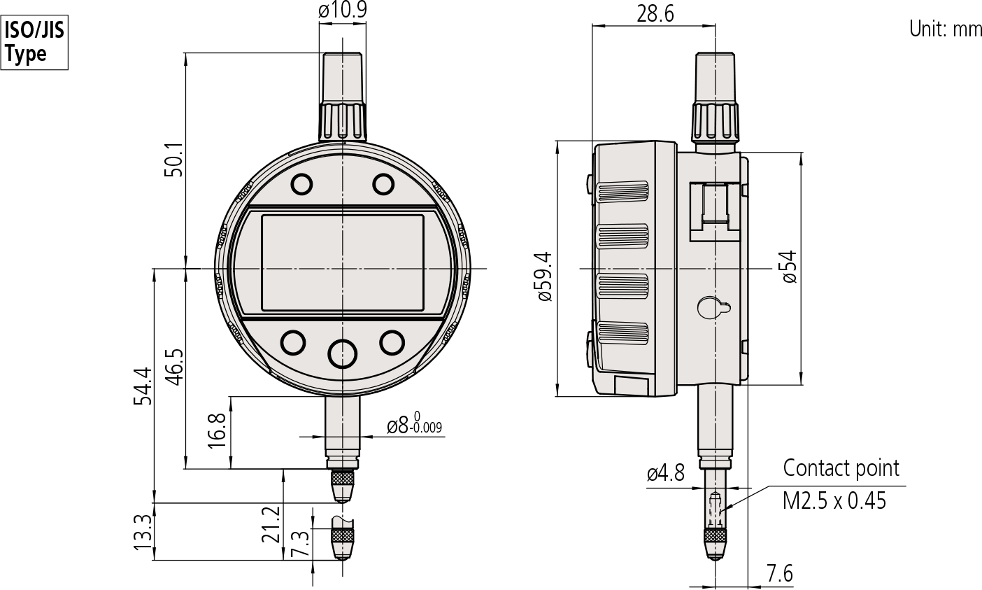
Note 1: Dimensions of the inch (ANSI/AGD Type) dial indicator partly differ from those of the metric (ISO/JIS Type) indicator.
Note 2: Inch (ANSI/AGD Type) dial indicators are provided with a stem of 3/8″ dia. and #4-48UNF thread mount for the contact point.
Fixture examples
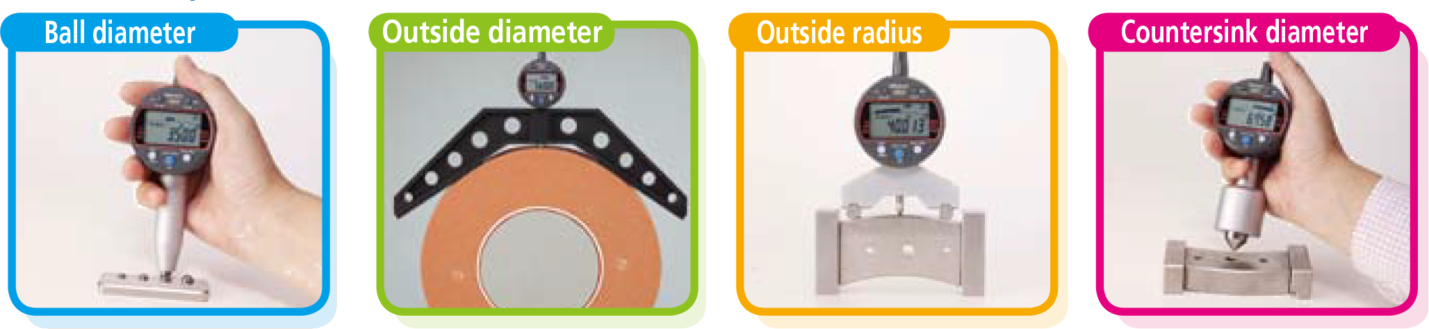
Examples of measuring various features
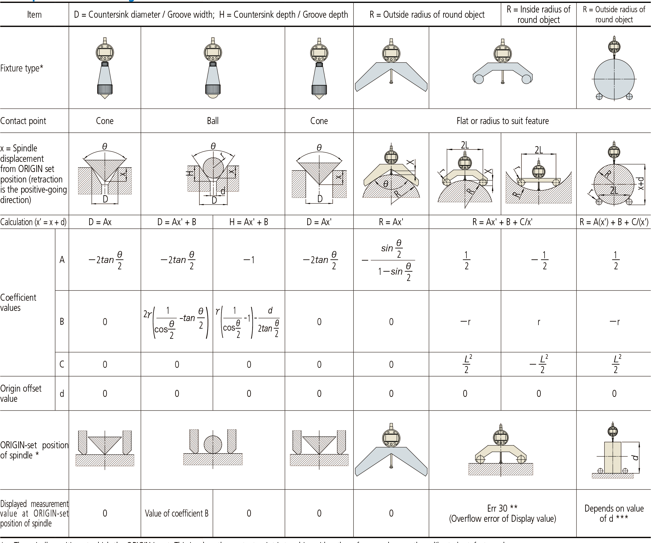
* The spindle position at which the ORIGIN is set. This is when the contact point is touching either the reference plane or the calibrated artefact, as shown.
** The ‘Err30’ message shown in the display is extinguished when the spindle is moved into the measurement range.
*** The value of d is chosen to suit the radius range to be measured, the stroke of the indicator and the best spindle position for the ORIGIN. Note that the value of x’ should not be allowed to approach zero as this is a highly non-linear region of the equation and measurement accuracy will deteriorate rapidly. A spreadsheet simulation will aid selection of the best value of d for particular r, L and R values.
Notes
1. Fixtures suited to individual workpieces can be made to order.
2. Measuring accuracy is subject to fixture accuracy and workpiece form accuracy.
Functions
Calculation function f (x’) = Ax’ + B + Cx’
(x’ = x + offset)
Peak detection function (Max/Min)
Runout value Hold function (difference between max.
and min. value motion)
Peak detection sampling rate (Switchable)
10 times/sec. (FAST Mode OFF)
50 times/sec. (FAST Mode ON)
Zeroset function (INC system)
Preset function (ABS system)
Tolerance judgement function (P1, P2, P3, and INC can be stored)
Analog bar resolution selectable function
Key lock function
Display hold function (when external device is connected)
Data output function
External PC setting input function (330°)
Low battery/voltage alarm display
Error alarm display
Resolution switching function*
Resolution (mm)
| 0.0002 | 0.005 | 0.1 |
| 0.0005 | 0.01 | 0.2 |
| 0.001 | 0.02 | 0.5 |
| 0.002 | 0.05 | 1 |
Resolution (inch)
| 0.00001 | 0.0002 | 0.005 |
| 0.00002 | 0.0005 | 0.01 |
| 0.00005 | 0.001 | 0.02 |
| 0.0001 | 0.002 | 0.05 |
*5: Since the calculation resolution is one micrometer
(0.001mm), using sub-micrometer resolution settings
may result in the 4th-place digit being unreliable,
particularly when B is set to a very low value
and C =0. It does not change at all with certain
combinations of calculation coefficient (for example,
A = 1, B = C =0). The 3rd-place digit representing
micrometers (if displayed) is always reliable.
Optional Accessories
• Lifting
Lifting lever:
No.21EZA198 (ISO/JIS/DIN Type),
No.21EZA199 (ASME/ANSI/ AGD Type)
Lifting knob:
No.21EZA105 (ISO/JIS/DIN Type),
No.21EZA150 (ASME/ANSI/ AGD Type)
Lifting cable : No. 540774
• SPC Cable:
No.905338 (1m)
No.905409 (2m)
• USB Input Tool Direct (2m) : No.06ADV380F
• Connecting Cables for U-WAVE-T (160mm) :
No.02AZD790F
For footswitch : No.02AZE140F
Refer to page F-60 for details.
• Digimatic Mini-Processor DP-1VR : 264-504
• Parameter setup kit : No.21EZA313
Note: Parameter setting software (can be downloaded freely from Mitutoyo website) is also required.
• Contact points for Mitutoyo’s dial indicators (Refer to pages F-51 to F-54 for details.)
• Measuring stands (Refer to page F-79 to F-85 for details.)