Call Us: +91-7972969901
Call Us: +91-7972969901
DIMENSIONS
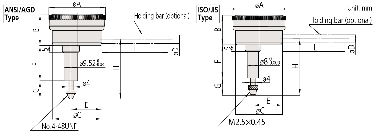
| Order No. | A | B | C | E | F | G | H |
|---|---|---|---|---|---|---|---|
| 1166T | 40 | 22.1 | 35.6 | 22.2 | 25 | 10.9 | 42 |
| 1167T | 40 | 22.1 | 35.6 | 22.2 | 25 | 10.9 | 42 |
| 1168T | 40 | 22.1 | 35.6 | 22.2 | 25 | 10.9 | 42 |
| 1961T | 40 | 22.1 | 35.6 | 22.2 | 25 | 10.9 | 40 |
| Order No. | A | B | C | E | F | G | H |
|---|---|---|---|---|---|---|---|
| 1160T | 40 | 22.1 | 35.6 | 22.2 | 25 | 13.8 | 43.3 |
| 1162T | 40 | 22.1 | 35.6 | 22.2 | 25 | 13.8 | 43.3 |
| 1960T | 40 | 22.1 | 35.6 | 22.2 | 28.7 | 12.8 | 46 |
Note 1:
Contact point (standard accessory) for all products in this page has a role as a top dead point stopper. For this reason, if you need to install an optional contact point with an outside diameter smaller than 7mm, use a washer (with outside diameter of at least 7mm, inside diameter of 3mm, and thickness of approx. 0.5mm) placed between the contact point and the spindle.
Note 2:
Dimensions of the inch (ANSI/AGD Type) dial indicator partly differ from those of the metric (ISO/JIS Type) indicator.
Note 3:
Inch (ANSI/AGD Type) dial indicators are provided with a stem of 3/8″ dia. and #4-48UNF thread mount for the contact point.
SPECIFICATIONS
Metric
| Order No. | Graduation | Range (range/rev) | Accuracy | Repeatbility | Dial reading | Measuring force | |||
|---|---|---|---|---|---|---|---|---|---|
| Overall | Retrace | 1/10 Rev | 1 Rev | ||||||
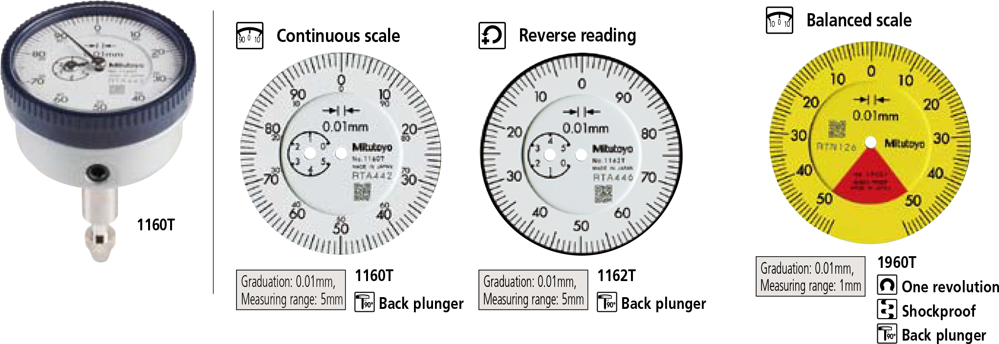
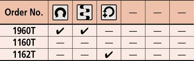
| 1960T | 0.01mm | 1mm (1.27mm) | 14µm | 4µm | 8µm | — | 3µm | 50-0-50 | 1.4N or less |
| 1160T | 0.01mm | 5mm (1mm) | 16µm | 4µm | 8µm | 14µm | 3µm | ±0-100 | 1.4N or less |
| 1162T | 0.01mm | 5mm (1mm) | 16µm | 4µm | 8µm | 14µm | 3µm | 100-0 | 1.4N or less |
* Completed products inspection is performed in the vertical position (contact point downward) and the stated accuracy is guaranteed.
Inch
| Order No. | Graduation | Range (range/rev) | Accuracy | Repeatbility | Dial reading | Measuring force | |
|---|---|---|---|---|---|---|---|
| First 1 Rev / 2.5 Rev / 10 Rev | Retrace | ||||||
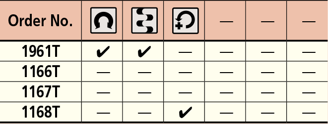
| 1961T | .001” | .04” (.05”) | ±.001” / — / — | .0002” | ±.0002” | 20-0-20 | 1.4N or less |
| 1166T | .001” | .2” (.05”) | ±.001” / ±.001” / ±.001” | .00033” | ±.0002” | ±0-50 | 1.4N or less |
| 1167T | .001” | .2” (.05”) | ±.001” / ±.001” / ±.001” | .00033” | ±.0002” | 0-25-0 | 1.4N or less |
| 1168T | .001” | .2” (.05”) | ±.001” / ±.001” / ±.001” | .00033” | ±.0002” | 50-0 | 1.4N or less |
* Completed products inspection is performed in the vertical position (contact point downward) and the stated accuracy is guaranteed.
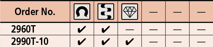
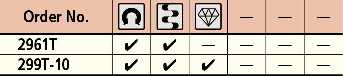
FEATURES
Metric
Inch
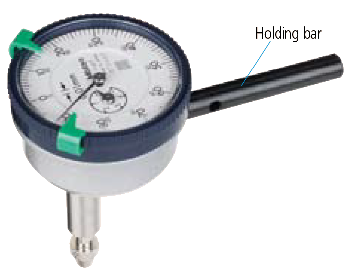
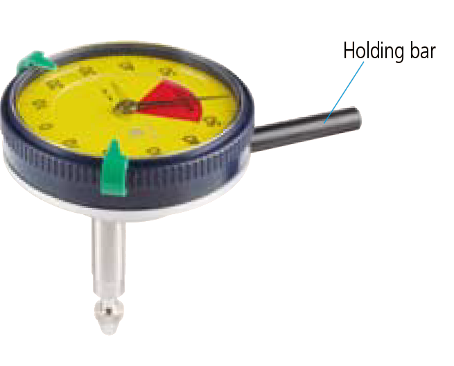
Holding bar (optional)
| Order No. | øD | L |
|---|---|---|
| 21AAA166 | ø6mm | 42mm |
| 136567 | ø6mm | 81mm |
| 124625 | ø6.35mm | 81mm |
| 21AAA167 | ø6.35mm | 42mm |
| 21AAA168 | ø8mm | 42mm |
| 136568 | ø8mm | 81mm |
* øD and L: detail shown in drawing below.
DIMENSIONS
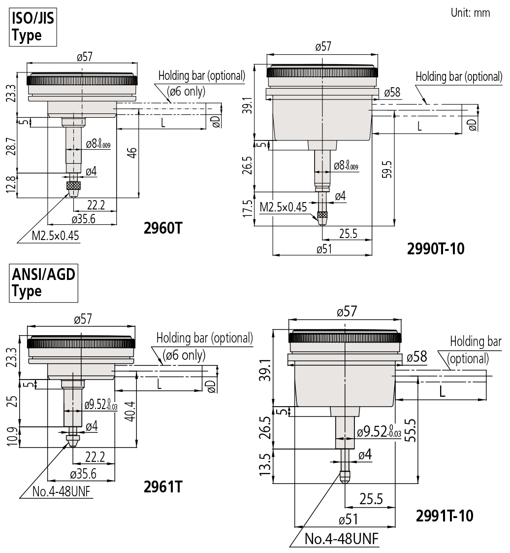
* The shoulder on a contact point (standard accessory) for 2960T and 2961T acts as a stop to prevent spindle overrun that may otherwise damage the indicator. For this reason, if you need to install an optional contact point with an outside diameter smaller than 7mm, use a washer (with outside diameter of at least 7mm, inside diameter of 3mm, and thickness of approx. 0.5mm) placed between the contact point and the spindle.
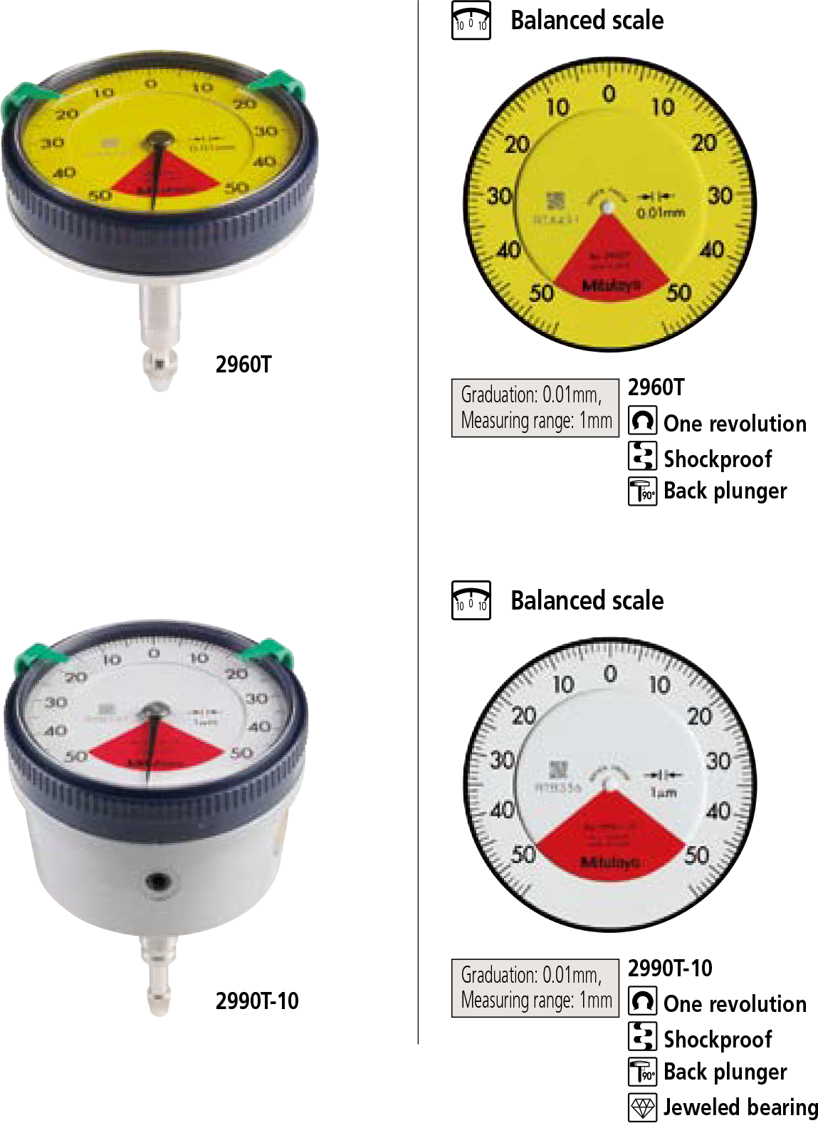
Metric
| Order No. | Graduation | Range (range/rev) | Accuracy | Repeatbility | Dial reading | Measuring force | |||
|---|---|---|---|---|---|---|---|---|---|
| Overall | Retrace | 1/10 Rev | 1 Rev | ||||||
| 2960T | 0.01mm | 1mm (1.27mm) | 14µm | 4µm | 8µm | — | 3µm | 50-0-50 | 1.4N or less |
| 2990T-10 | 0.001mm | 0.1mm (0.14mm) | 5µm | 2µm | 2.5µm | — | 1µm | 50-0-50 | 1.5N or less |
* Completed products inspection is performed in the vertical position (contact point downward) and the stated accuracy is guaranteed.
Inch
| Order No. | Graduation | Range (range/rev) | Accuracy | Repeatbility | Dial reading | Measuring force | |
|---|---|---|---|---|---|---|---|
| First 1 Rev / 2.5 Rev / 10 Rev | Retrace | ||||||
| 2961T | .0005” | .04” / .05” | ±.0005” / — / — | .00016” | ±.0001” | 20-0-20 | 1.4N or less |
| 2991T-10 | .0001” | .008” / .01” | ±.0002” / — / — | .0001” | ±.00005” | 4-0-4 | 1.5N or less |
* Completed products inspection is performed in the vertical position (contact point downward) and the stated accuracy is guaranteed.
Metric
Inch
Holding bar (optional)
| Order No. | øD | L |
|---|---|---|
| 21AAA166 | ø6mm | 42mm |
| 136567 | ø6mm | 81mm |
| 124625 | ø6.35mm | 81mm |
| 21AAA167 | ø6.35mm | 42mm |
| 21AAA168 | ø8mm | 42mm |
| 136568 | ø8mm | 81mm |
* øD and L: detail shown in drawing below.