Call Us: +91-7972969901
Call Us: +91-7972969901
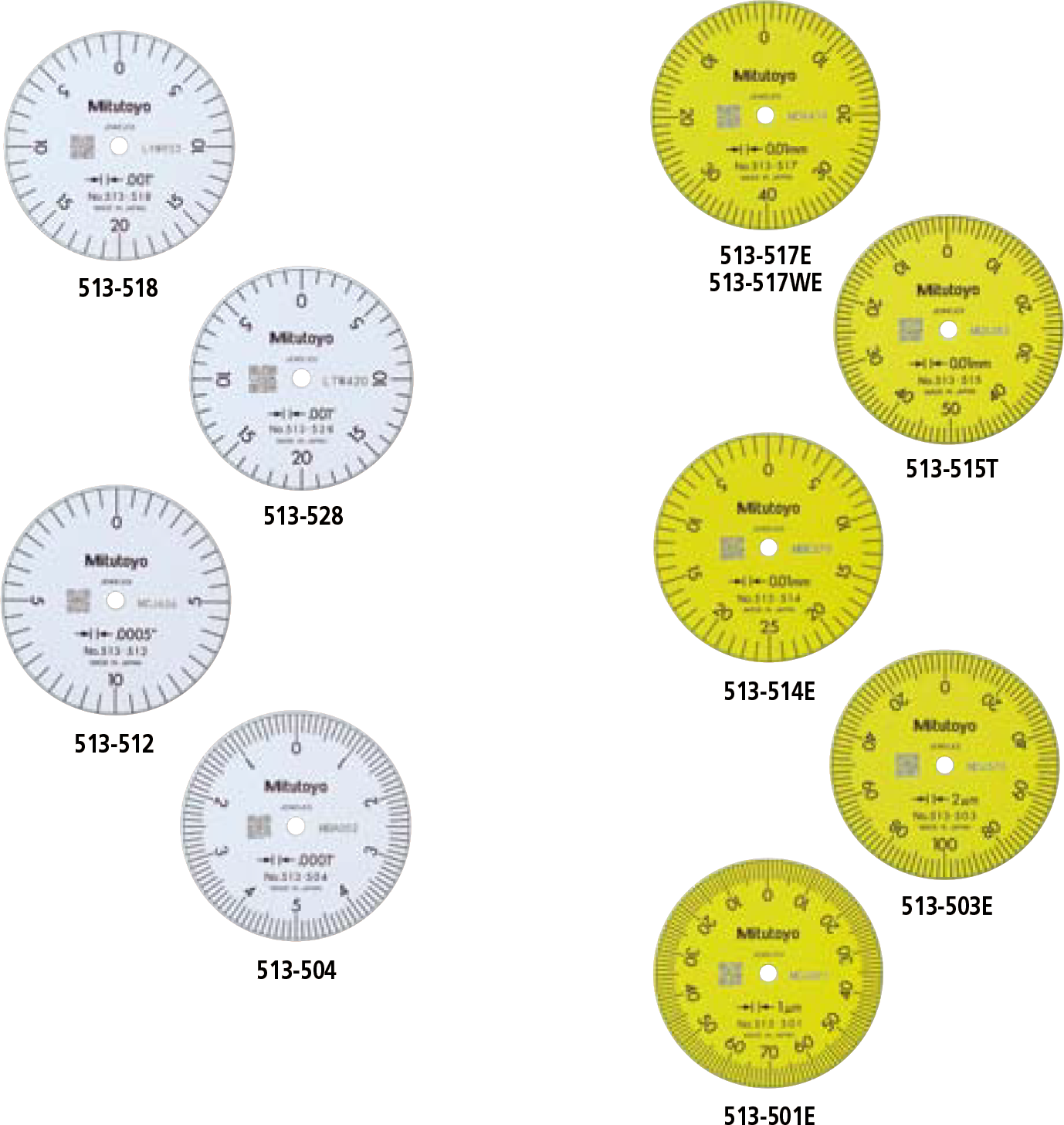
Styli (for Metric Models Only*)
* Except for universal type dial test indicator (513-304G).
ø0.5mm ball-point
190547 (L=14.7mm)
190549 (L=20.9mm)
190654 (L=22.3mm)
190656 (L=44.5mm)
ø0.7mm ball-point
![]()
190548 (L=14.7mm)
190550 (L=20.9mm)
190653 (L=22.3mm)
190655 (L=44.5mm)
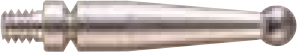
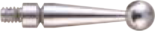
ø1mm ball-point (Carbide)
![]()
21CZA044 (L=12.8mm)
103017 (L=14.7mm)
103013 (L=20.9mm)
137558 (L=22.3mm)
137746 (L=36.8mm)
136235 (L=44.5mm)
ø2mm ball-point (Carbide)
21CZA036 (L=12.8mm)
103010 (L=14.7mm)
103006 (L=20.9mm)
137557 (L=22.3mm)
129949 (L=36.8mm)
136013 (L=44.5mm)
ø2mm ball-point (Ruby)
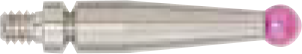
21CZA212 (L=12.8mm)
21CZA209 (L=14.7mm)
21CZA201 (L=20.9mm)
21CZA210 (L=22.3mm)
21CZA211 (L=44.5mm)
ø3mm ball-point (Carbide)
21CZA045 (L=12.8mm)
103018 (L=14.7mm)
103014 (L=20.9mm)
137559 (L=22.3mm)
137747 (L=36.8mm)
136236 (L=44.5mm)
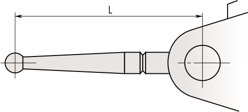
Spanner
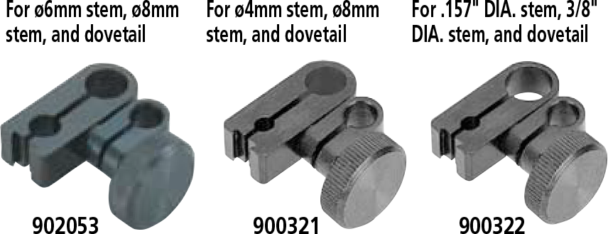
Stems with Knurled Clamp Ring

Swivel Clamps
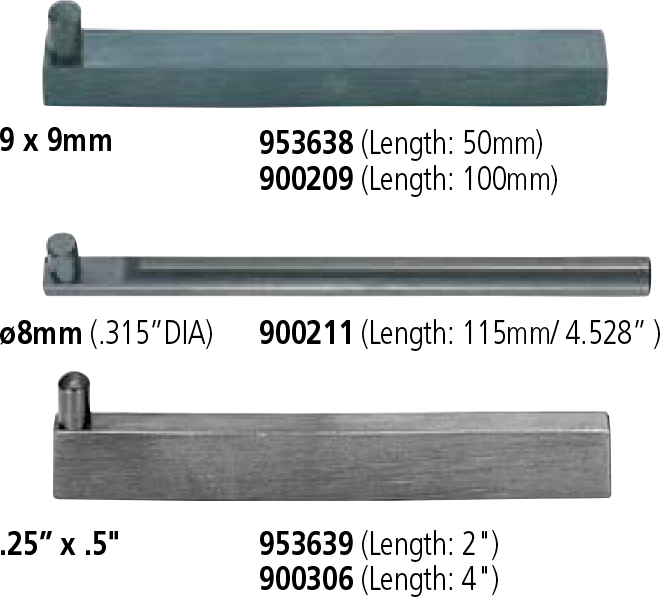
Holding Bars
Universal Holder
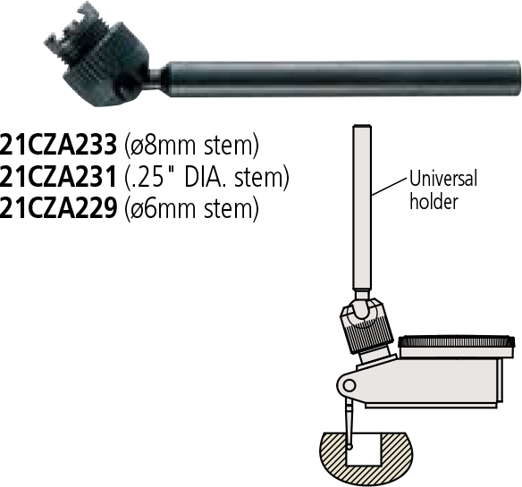
21CZA233 (ø8mm stem)
21CZA231 (.25″ DIA. stem)
21CZA229 (ø6mm stem)
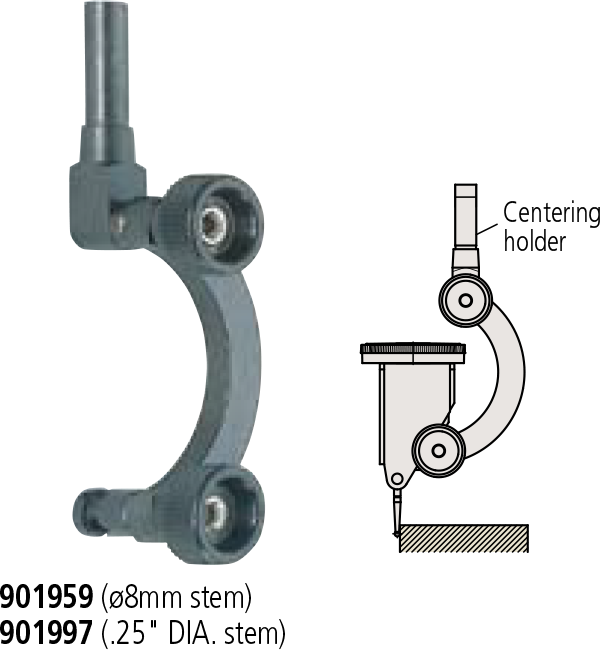
Centering Holder

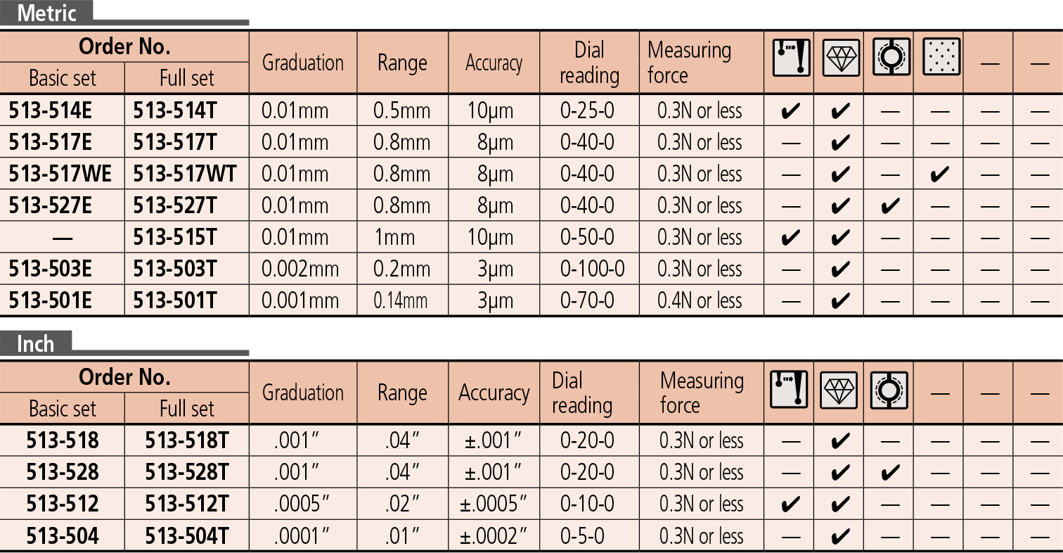
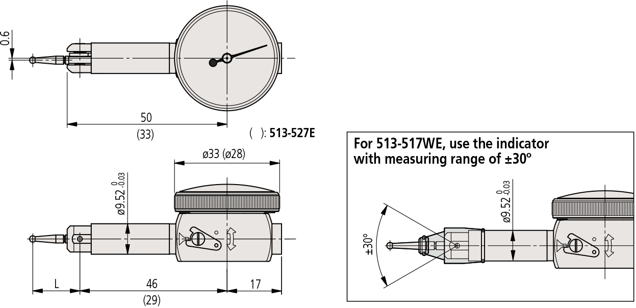
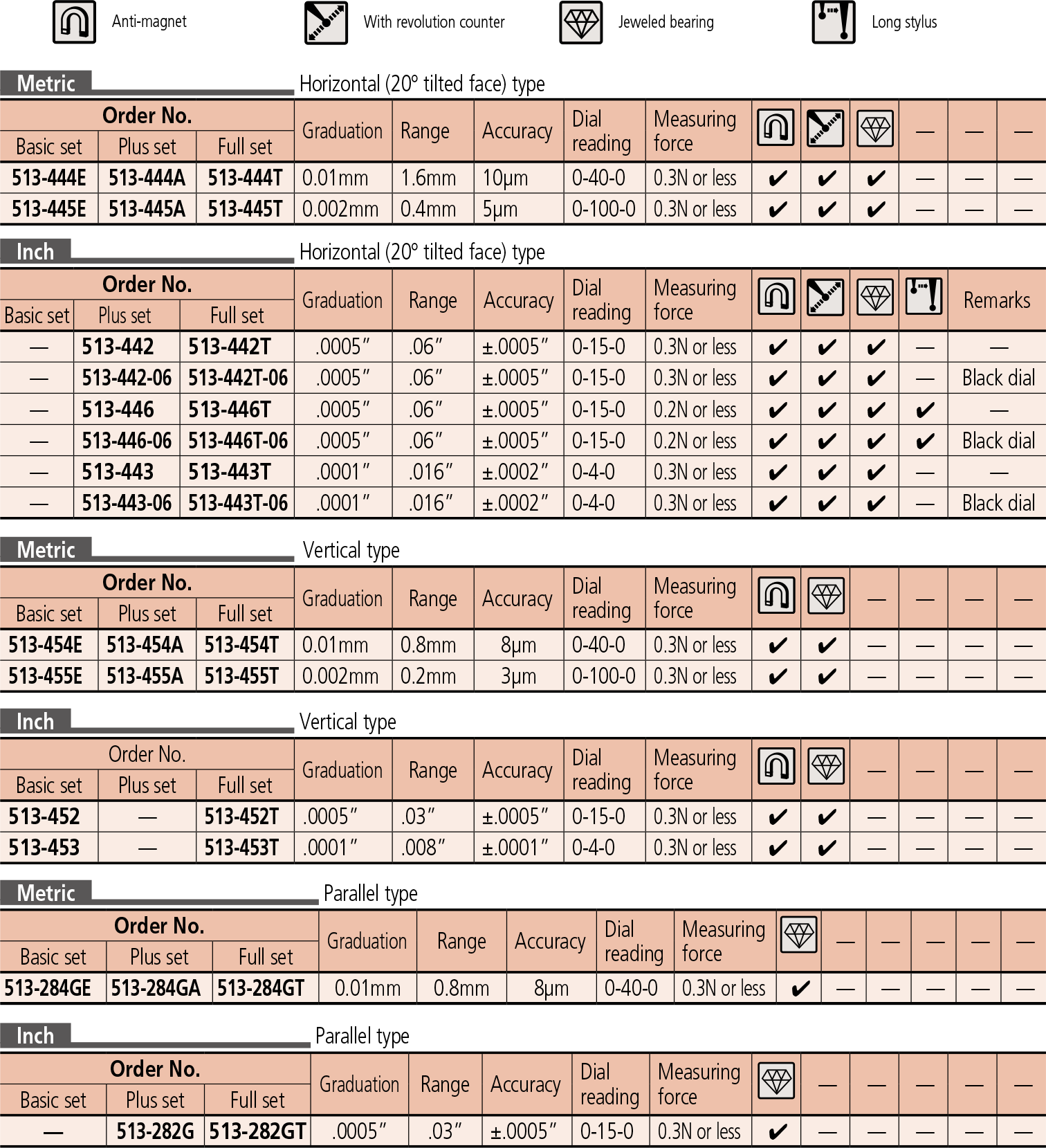
SPECIFICATIONS
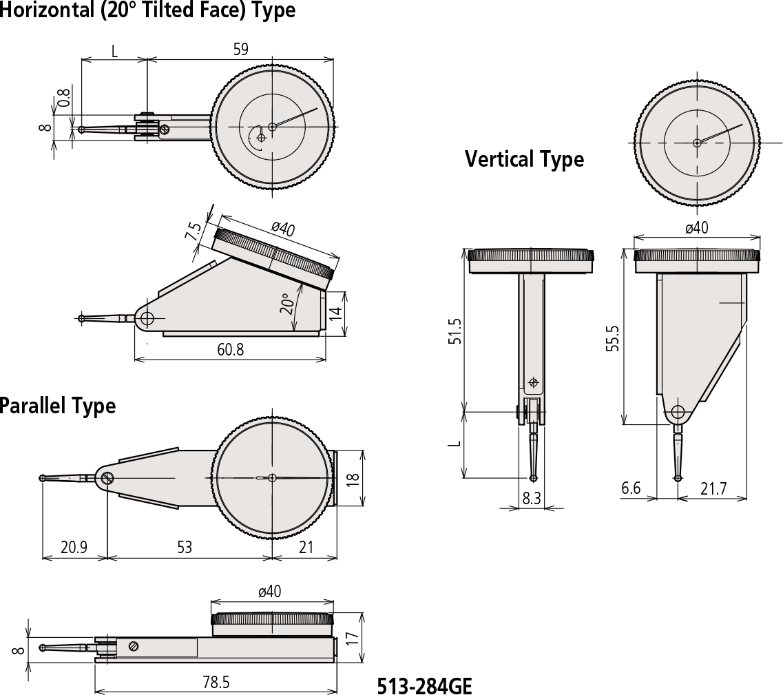
DIMENSIONS
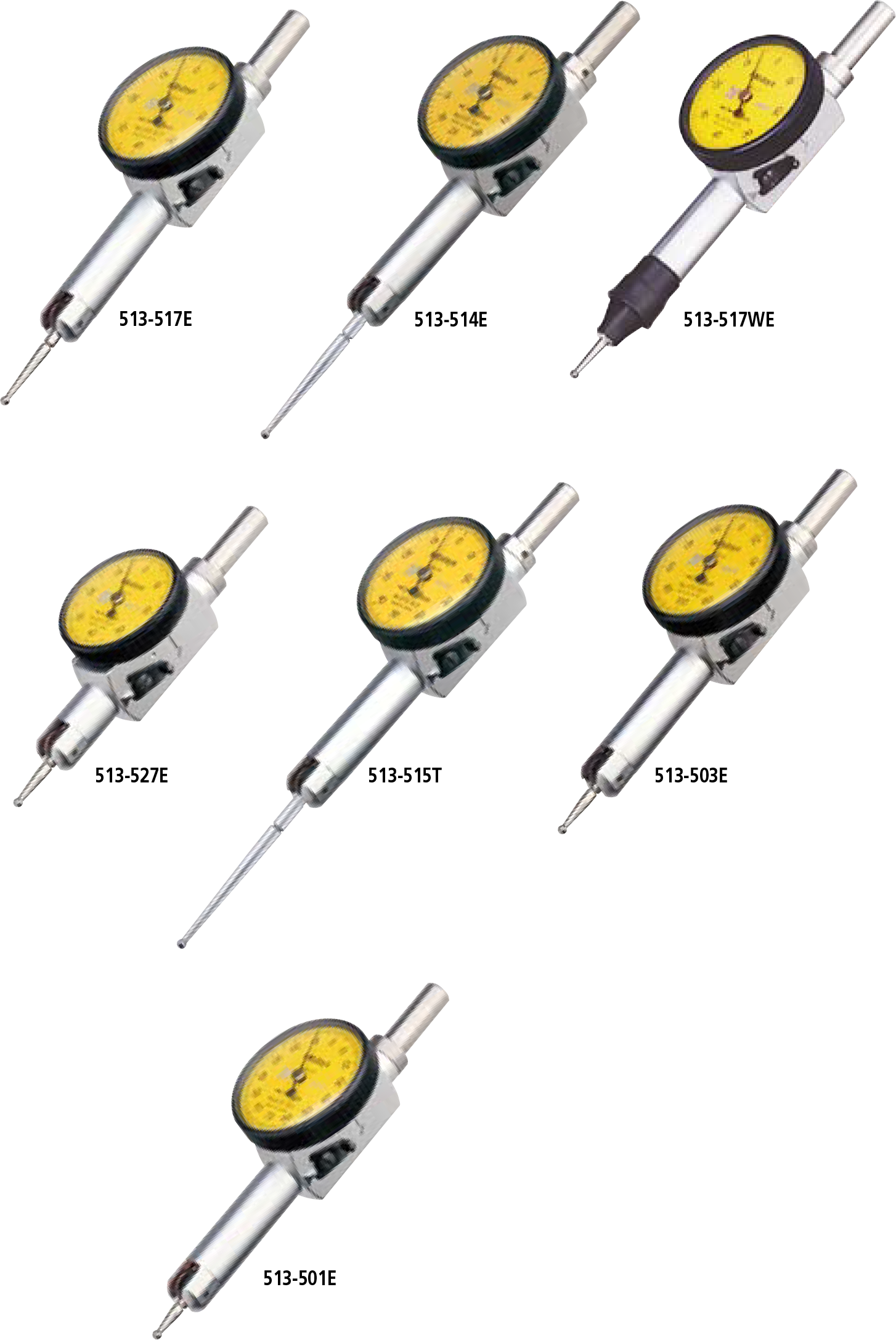
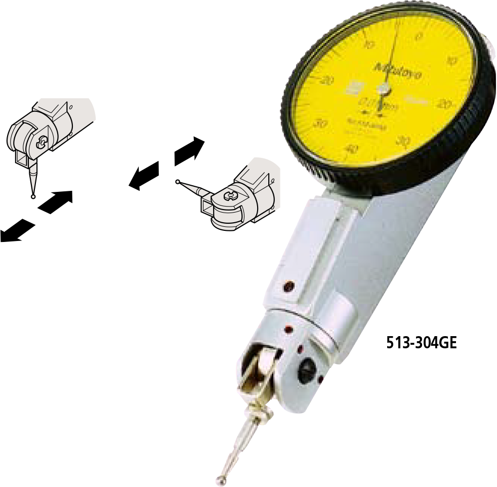
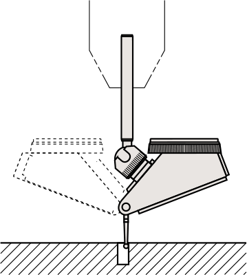
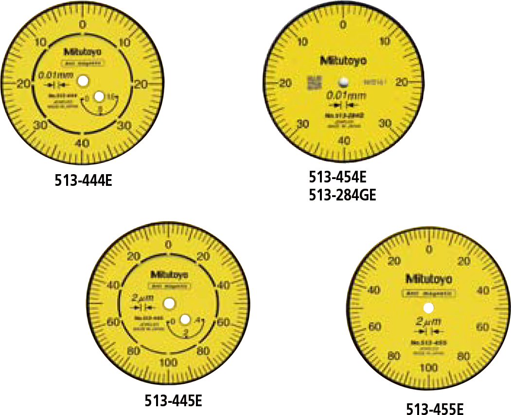
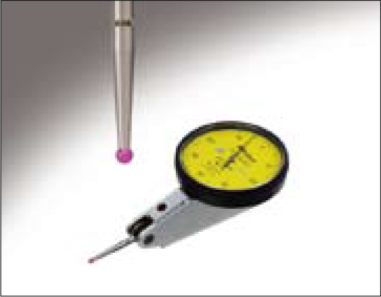
There are two types of Mitutoyo Dial Test Indicator: The non-clutch type (without a clutch lever) and the clutch type (with a two-position clutch lever)
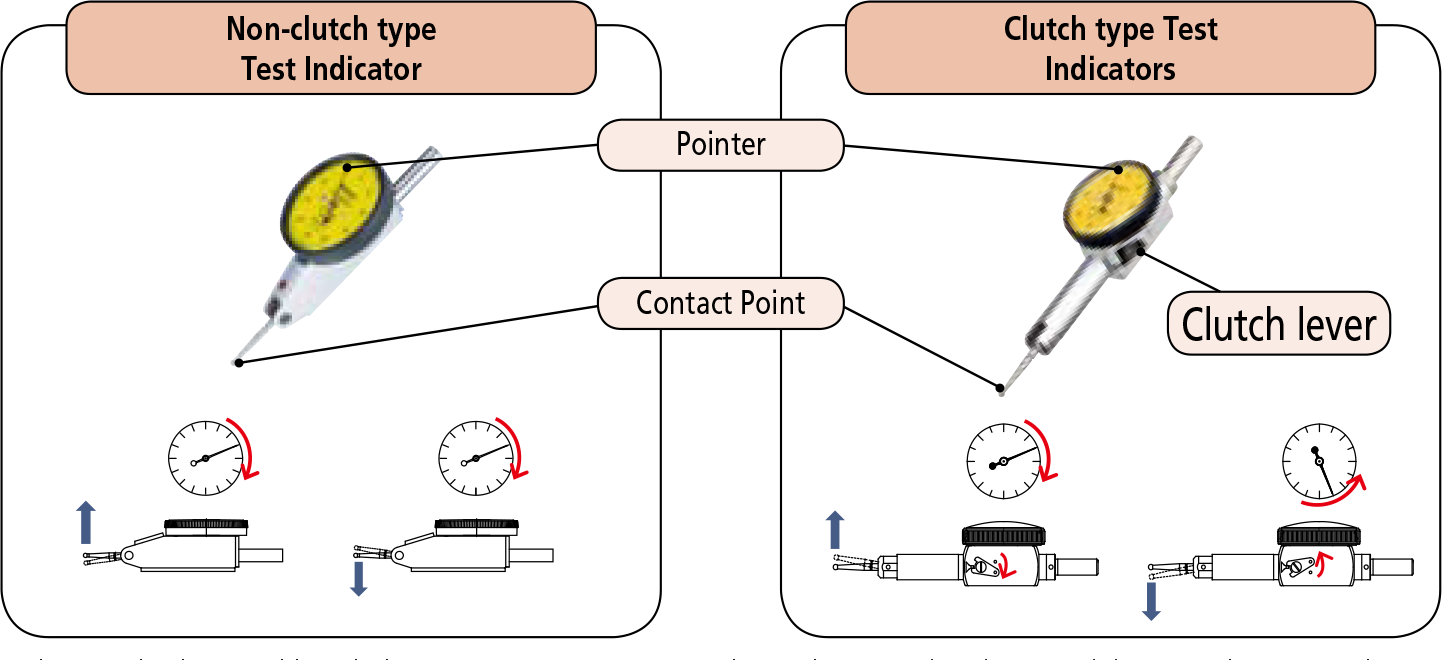
In the non-clutch type, although the contact point may move either in the upward or downward direction, the pointer always rotates clockwise. In the clutch type, if the clutch lever is set in one position the contact point moves in the upward direction and the pointer rotates clockwise. Conversely, if the lever is set in the other position the contact point moves in the downward direction and the pointer rotates counterclockwise.
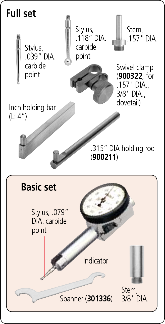
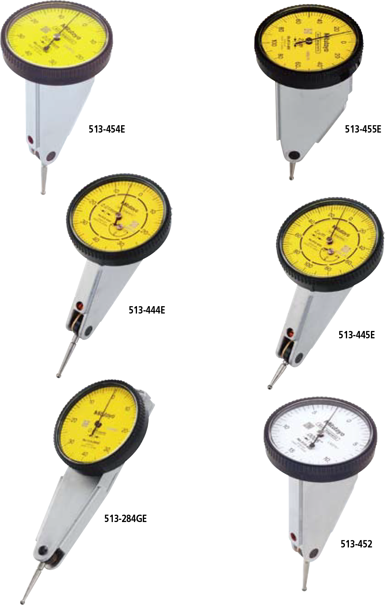
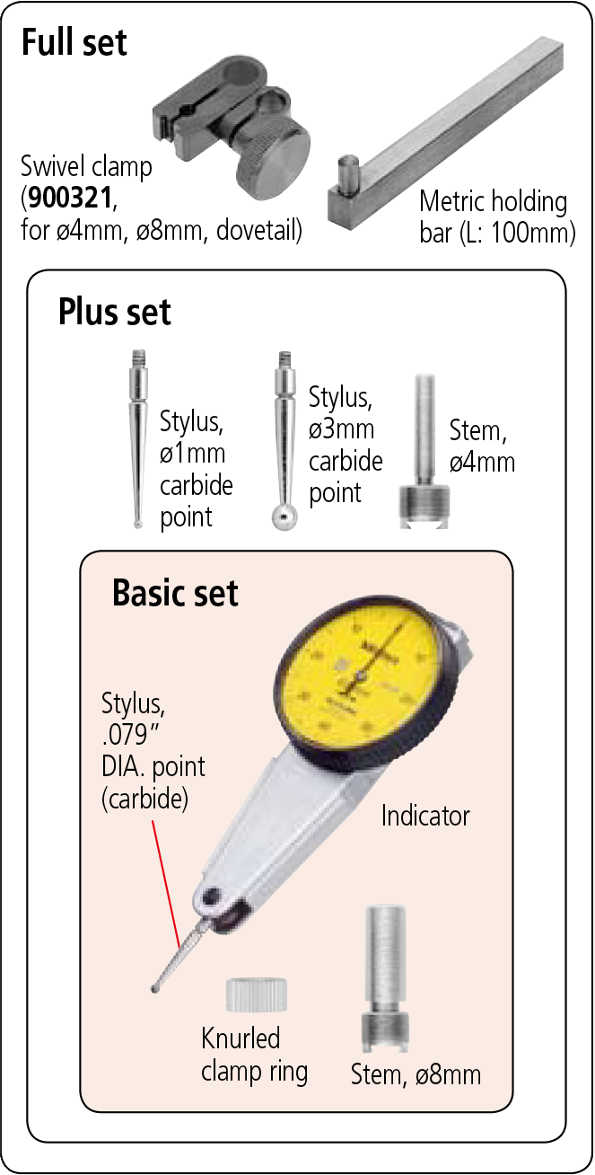
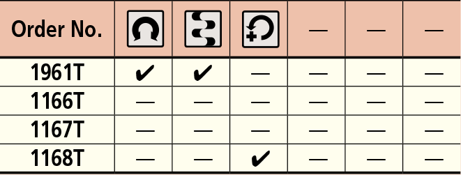
Set Configuration: Metric
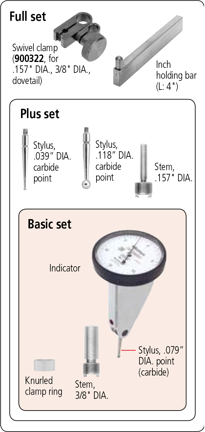
Set Configuration: Inch
SPECIFICATIONS
DIMENSIONS
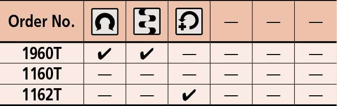
Set Configuration: Metric
Set Configuration: Inch
Optional Accessories
––––––: Swivel clamps (See page F-63.)
––––––: Holding bars (See page F-63.)
––––––: Stems (See page F-63.)
102824: Stylus, ø1mm ball contact (carbide)
102825: Stylus, ø2mm ball contact (carbide)
102826: Stylus, ø3mm ball contact (carbide)
The dial face obliquely faces upward, allowing users to read the graduations from the user’s side. It is convenient when probing on the side of a large workpiece and the workbench is high.
Using the universal holder allows easy hole centering. The dial face always faces upward when the indicator is rotated, which makes reading easy.
SPECIFICATIONS
DIMENSIONS
Set Configuration: Metric
Set Configuration: Inch
Optional Accessories
––––––: Swivel clamps (See page F-63.)
––––––: Holding bars (See page F-63.)
––––––: Stems (See page F-63.)
––––––: Styli (See page F-63.)
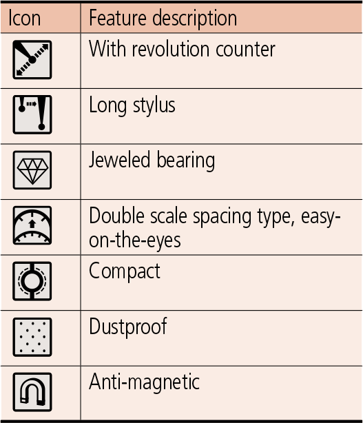
Feature icons
DIMENSIONS
| Order No. | A | B | C | E | F | G | H |
|---|---|---|---|---|---|---|---|
| 1166T | 40 | 22.1 | 35.6 | 22.2 | 25 | 10.9 | 42 |
| 1167T | 40 | 22.1 | 35.6 | 22.2 | 25 | 10.9 | 42 |
| 1168T | 40 | 22.1 | 35.6 | 22.2 | 25 | 10.9 | 42 |
| 1961T | 40 | 22.1 | 35.6 | 22.2 | 25 | 10.9 | 40 |
| Order No. | A | B | C | E | F | G | H |
|---|---|---|---|---|---|---|---|
| 1160T | 40 | 22.1 | 35.6 | 22.2 | 25 | 13.8 | 43.3 |
| 1162T | 40 | 22.1 | 35.6 | 22.2 | 25 | 13.8 | 43.3 |
| 1960T | 40 | 22.1 | 35.6 | 22.2 | 28.7 | 12.8 | 46 |
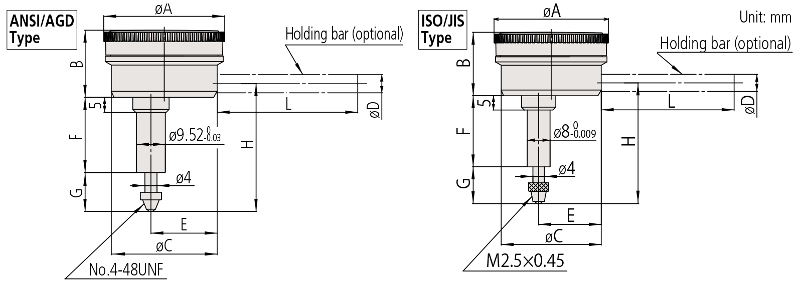
Note 1:
Contact point (standard accessory) for all products in this page has a role as a top dead point stopper. For this reason, if you need to install an optional contact point with an outside diameter smaller than 7mm, use a washer (with outside diameter of at least 7mm, inside diameter of 3mm, and thickness of approx. 0.5mm) placed between the contact point and the spindle.
Note 2:
Dimensions of the inch (ANSI/AGD Type) dial indicator partly differ from those of the metric (ISO/JIS Type) indicator.
Note 3:
Inch (ANSI/AGD Type) dial indicators are provided with a stem of 3/8″ dia. and #4-48UNF thread mount for the contact point.
SPECIFICATIONS
Metric
| Order No. | Graduation | Range (range/rev) | Accuracy | Repeatbility | Dial reading | Measuring force | |||
|---|---|---|---|---|---|---|---|---|---|
| Overall | Retrace | 1/10 Rev | 1 Rev | ||||||
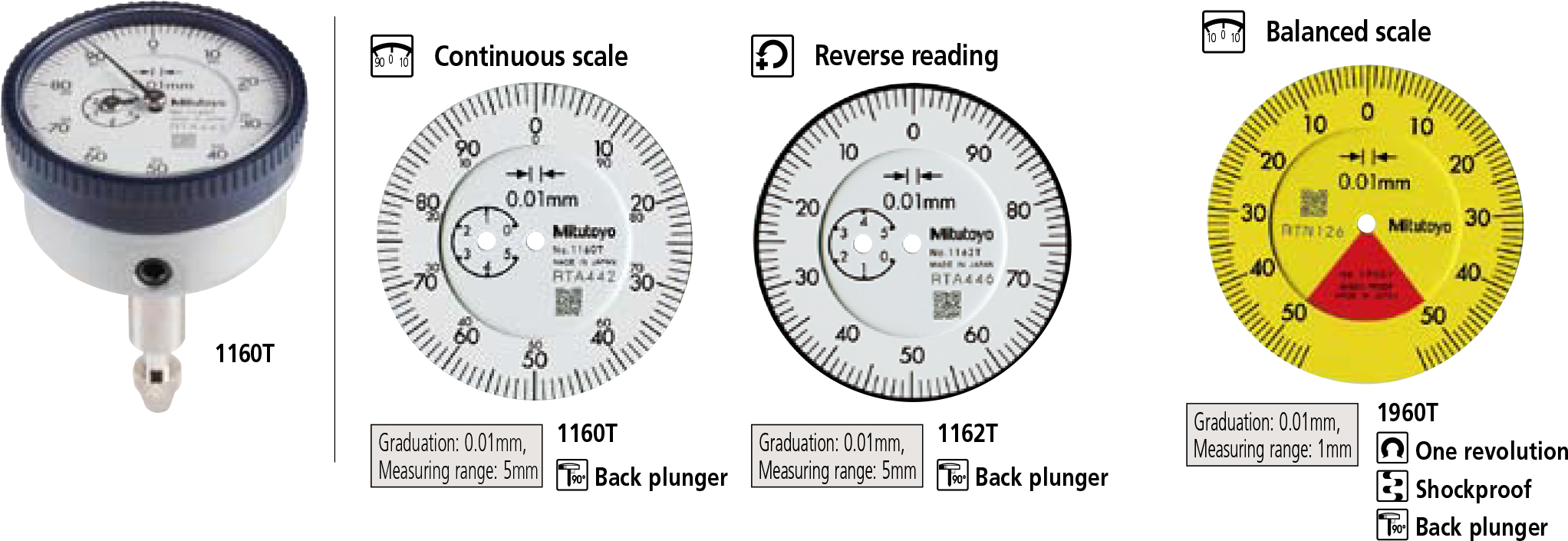
| 1960T | 0.01mm | 1mm (1.27mm) | 14µm | 4µm | 8µm | — | 3µm | 50-0-50 | 1.4N or less |
| 1160T | 0.01mm | 5mm (1mm) | 16µm | 4µm | 8µm | 14µm | 3µm | ±0-100 | 1.4N or less |
| 1162T | 0.01mm | 5mm (1mm) | 16µm | 4µm | 8µm | 14µm | 3µm | 100-0 | 1.4N or less |
* Completed products inspection is performed in the vertical position (contact point downward) and the stated accuracy is guaranteed.
Inch
| Order No. | Graduation | Range (range/rev) | Accuracy | Repeatbility | Dial reading | Measuring force | |
|---|---|---|---|---|---|---|---|
| First 1 Rev / 2.5 Rev / 10 Rev | Retrace | ||||||
| 1961T | .001” | .04” (.05”) | ±.001” / — / — | .0002” | ±.0002” | 20-0-20 | 1.4N or less |
| 1166T | .001” | .2” (.05”) | ±.001” / ±.001” / ±.001” | .00033” | ±.0002” | ±0-50 | 1.4N or less |
| 1167T | .001” | .2” (.05”) | ±.001” / ±.001” / ±.001” | .00033” | ±.0002” | 0-25-0 | 1.4N or less |
| 1168T | .001” | .2” (.05”) | ±.001” / ±.001” / ±.001” | .00033” | ±.0002” | 50-0 | 1.4N or less |
* Completed products inspection is performed in the vertical position (contact point downward) and the stated accuracy is guaranteed.
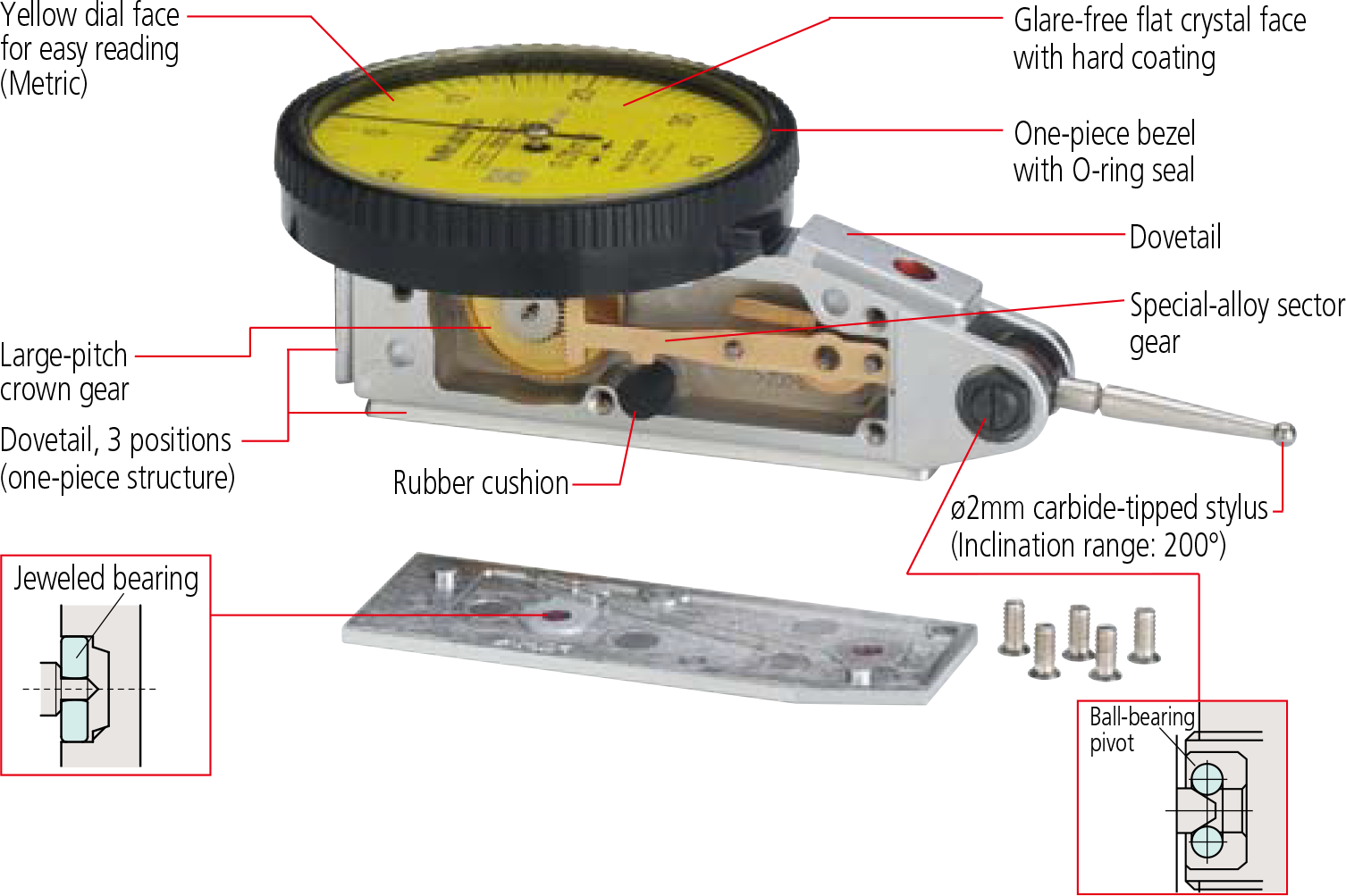
FEATURES
Metric
Inch
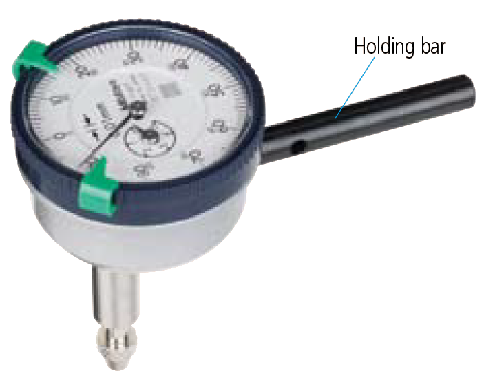
Holding bar (optional)
| Order No. | øD | L |
|---|---|---|
| 21AAA166 | ø6mm | 42mm |
| 136567 | ø6mm | 81mm |
| 124625 | ø6.35mm | 81mm |
| 21AAA167 | ø6.35mm | 42mm |
| 21AAA168 | ø8mm | 42mm |
| 136568 | ø8mm | 81mm |
* øD and L: detail shown in drawing below.