Call Us: +91-7972969901
Call Us: +91-7972969901
Note:
Odd pitch and diameter combination, extra fine pitch gauges also manufactured.
 |
||
 |
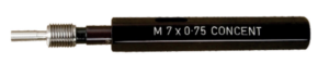 |
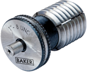
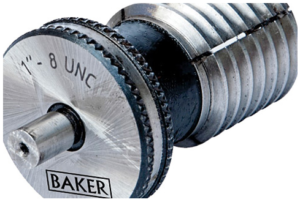
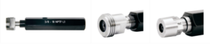
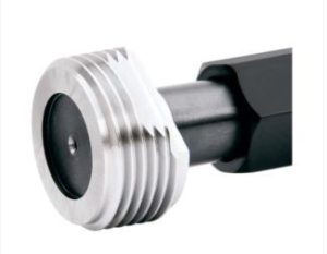
Baker manufactures hole location plugs as shown. These are used to measure & check the location of small tapped holes. This is a perfect thread gauge to inspect features for run-out to the pitch diameter of the threads. These give a firm locating grip without pulling the shoulder of the plug up against the hole face thus avoiding squareness errors.
Hole location plugs are commonly used to measure the location of tapped holes. It is difficult to accurately measure the location of tapped holes using conventional methods; i.e. CMM’s or indicating type instruments. Hole location plugs are deliberately manufactured with Pitch diameter over-size, then slitted, resulting in the threaded section collapsing while being screwed in the threaded hole. The hole location plug will screw in tightly, locating on the Pitch diameter of the tapped hole. A measurement can then be taken from the datum point to the cylindrical diameter on the hole location plug to determine location. For very small sizes, the plug is not slitted but the thread is manufactured with a gradual taper, which will lock up on the thread.
 |
 |
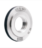
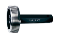
Line Pipe Thread Gauges
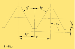
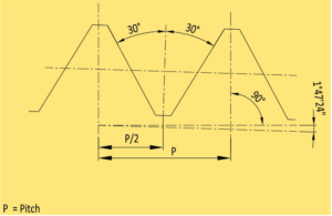
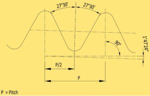
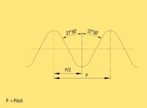
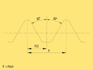
Thread angle 60°
| Size | T.P.I. | Taper |
|---|---|---|
| ⅛ | 27 | 1 : 16 |
| ¼ | 18 | 1 : 16 |
| ⅜ | 18 | 1 : 16 |
| ½ | 14 | 1 : 16 |
| ¾ | 14 | 1 : 16 |
| 1 | 11½ | 1 : 16 |
| 1¼ | 11½ | 1 : 16 |
| 1½ | 11½ | 1 : 16 |
| 2 | 11½ | 1 : 16 |
| 2½ | 8 | 1 : 16 |
| 3 | 8 | 1 : 16 |
| 3½ | 8 | 1 : 16 |
| 4 | 8 | 1 : 16 |
| 5 | 8 | 1 : 16 |
| 6 | 8 | 1 : 16 |
| 8 | 8 | 1 : 16 |
| 10 | 8 | 1 : 16 |
| 12 | 8 | 1 : 16 |
| 14D | 8 | 1 : 16 |
| 16D | 8 | 1 : 16 |
| 18D | 8 | 1 : 16 |
| 20D | 8 | 1 : 16 |
Casing Round Thread Gauges
Thread angle 60°
| Size | T.P.I. | Taper |
|---|---|---|
| 4 ½ | *8 | 1 : 16 |
| 5 | *8 | 1 : 16 |
| 5 ½ | *8 | 1 : 16 |
| 6 | *8 | 1 : 16 |
| 7 | *8 | 1 : 16 |
| 7 ⅝ | *8 | 1 : 16 |
| 8 ⅝ | *8 | 1 : 16 |
| 9 ⅝ | *8 | 1 : 16 |
| 10 ¾ | 8 | 1 : 16 |
| 11 ¾ | 8 | 1 : 16 |
| 13 ⅜ | 8 | 1 : 16 |
| 16 | 8 | 1 : 16 |
| 18 ⅝ | 8 | 1 : 16 |
| 20 | *8 | 1 : 16 |
Buttress Casing Thread Gauges
Thread angle 3° x 10°
| Size | T.P.I. | Taper |
|---|---|---|
| 4 ½ | 5 | 1 : 16 |
| 5 | 5 | 1 : 16 |
| 5 ½ | 5 | 1 : 16 |
| 6 ⅝ | 5 | 1 : 16 |
| 7 | 5 | 1 : 16 |
| 7 ⅝ | 5 | 1 : 16 |
| 8 ⅝ | 5 | 1 : 16 |
| 9 ⅝ | 5 | 1 : 16 |
| 10 ¾ | 5 | 1 : 16 |
| 11 ¾ | 5 | 1 : 16 |
| 13 ⅜ | 5 | 1 : 16 |
| 16 | 5 | 1 : 12 |
| 18 ⅝ | 5 | 1 : 12 |
| 20 | 5 | 1 : 12 |
Non-Upset Tubing Thread Gauges
Thread angle 60°
| Size | T.P.I. | Taper |
|---|---|---|
| 1.050 | 10 | 1 : 16 |
| 1.315 | 10 | 1 : 16 |
| 1.660 | 10 | 1 : 16 |
| 1.900 | 10 | 1 : 16 |
| 2 ⅜ | 10 | 1 : 16 |
| 2 ⅞ | 10 | 1 : 16 |
| 3 ½ | 10 | 1 : 16 |
| 4 | 8 | 1 : 16 |
| 4 ½ | 8 | 1 : 16 |
External-Upset Tubing Thread Gauges
Thread angle 60°
| Size | T.P.I. | Taper |
|---|---|---|
| 1.050 | 10 | 1 : 16 |
| 1.315 | 10 | 1 : 16 |
| 1.660 | 10 | 1 : 16 |
| 1.900 | 10 | 1 : 16 |
| 2 ⅜ | 8 | 1 : 16 |
| 2 ⅞ | 8 | 1 : 16 |
| 3 ½ | 8 | 1 : 16 |
| 4 | 8 | 1 : 16 |
| 4 ½ | 8 | 1 : 16 |
Extreme-Line Casing Thread & Seal Gauges
Thread angle 6° x 6°
| Size | T.P.I. | Taper |
|---|---|---|
| 5 | 6 | 1 : 8 |
| 5 ½ | 6 | 1 : 8 |
| 6 ⅝ | 6 | 1 : 8 |
| 7 | 6 | 1 : 8 |
| 7 ⅝ | 6 | 1 : 8 |
| 8 ⅝ | 5 | 1 : 9.6 |
| 9 ⅝ | 5 | 1 : 9.6 |
| 10 ¾ | 5 | 1 : 9.6 |
Number Style
Thread angle 60°
| Size | T.P.I. | Taper |
|---|---|---|
| NC 23 | 4 | 1 : 6 |
| NC 26 | 4 | 1 : 6 |
| NC 31 | 4 | 1 : 6 |
| NC 35 | 4 | 1 : 6 |
| NC 38 | 4 | 1 : 6 |
| NC 40 | 4 | 1 : 6 |
| NC 44 | 4 | 1 : 6 |
| NC 46 | 4 | 1 : 6 |
| NC 50 | 4 | 1 : 6 |
| NC 56 | 4 | 1 : 4 |
| NC 61 | 4 | 1 : 4 |
| NC 70 | 4 | 1 : 4 |
| NC 77 | 4 | 1 : 4 |
Regular Style (Right or Left hand)
Thread angle 60°
| Size | T.P.I. | Taper |
|---|---|---|
| 1 | 6 | 1 : 8 |
| 1 ½ | 6 | 1 : 8 |
| 2 ⅜ | 5 | 1 : 4 |
| 2 ⅞ | 5 | 1 : 4 |
| 3 ½ | 5 | 1 : 4 |
| 4 ½ | 5 | 1 : 4 |
| 5 ½ | 4 | 1 : 4 |
| 6 ⅝ | 4 | 1 : 6 |
| 7 ⅝ | 4 | 1 : 4 |
| 8 ⅝ | 4 | 1 : 4 |
Full-hole Style
Thread angle 60°
| Size | T.P.I. | Taper |
|---|---|---|
| 3 ½ | 5 | 1 : 4 |
| 4 | 4 | 1 : 6 |
| 4 ½ | 5 | 1 : 4 |
| 5 ½ | 4 | 1 : 6 |
| 6 ⅝ | 4 | 1 : 6 |
Internal-Flush Style
Thread angle 60°
| Size | T.P.I. | Taper |
|---|---|---|
| 2 ⅜ | 4 | 1 : 6 |
| 2 ⅞ | 4 | 1 : 6 |
| 3 ½ | 4 | 1 : 6 |
| 4 | 4 | 1 : 6 |
| 4 ½ | 4 | 1 : 6 |
| 5 ½ | 4 | 1 : 6 |
 |
 |
| Gauge dimensions are as per ASME B1.20.1. Gauges are supplied as Basic Step & Min/Max Step. |
– |
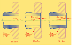
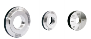
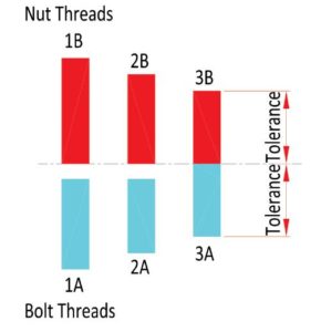
| GAUGING EXTERNAL THREADS | GAUGING INTERNAL THREADS |
| With basic step Ring gauge | With basic step Plug gauge |
 |
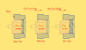 |
The Basic Step gauge when screwed onto the threads of the component by hand, should be flush with the endof the component face within 1 turn, as shown above.
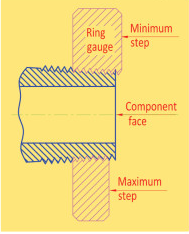
| With Min/Max step Ring gauge | With Min/Max step Plug gauge |
 |
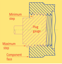 |
When using a Min/Max Step type gauge, the end of the component face should be flush between the Minimum and Maximum steps.
NPTF Threads are also known as Dryseal threads as they do not require a sealant to form a leak-proof joint.
| Type | Standard | Plug gauges | Ring gauges |
|---|---|---|---|
| NPFT | ANSI/ASME B 1.20.5 | Thread plug gauges L1 & L3 (Basic Step or Min/Max Step) 6 Step Crest Check Plug |
Thread ring gauges L1 & L2 (Basic Step or Min/Max Step) 6 Step Crest Check ring |
| ANPT | SAE SA71051B | Thread plug gauges L1 & L3 (Basic Step or Min/Max Step) 6 Step Crest Check Plug |
Thread ring gauges L1 & L2 (Basic Step or Min/Max Step) 6 Step Crest Check ring |
 |
 |
 |
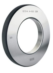
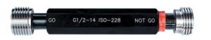
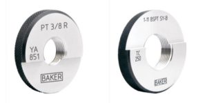
These are pipe threads where pressure-tight joints are not made on threads. Gauge dimensions are as per ISO 228-2
| Tolerance class | |
|---|---|
| Therad Ring gauge | A’ & ‘B’ |
| Therad Plug gauge | – |
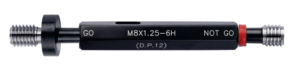
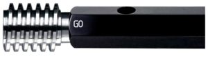
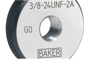
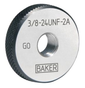
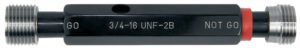
The GO gauge when screwed by hand without using excessive force, should enter and pass the whole length of the workpiece thread. The NOT GO gauge when screwed by hand without using excessive force, should not enter the component by more than two turns of the thread from both ends.
The GO gauge when screwed by hand without using excessive force, should enter and pass the whole length of the workpiece thread. The NOT GO gauge when screwed by hand without being forced, should not enter the component by more than three complete turns.
 |
 |
 |