Call Us: +91-7972969901
Call Us: +91-7972969901

SPECIFICATIONS
Metric
| Order No. (w/ lug, flat-back) | Range | Resolution | Overall accuracy* | Measuring force | Remarks | |
|---|---|---|---|---|---|---|
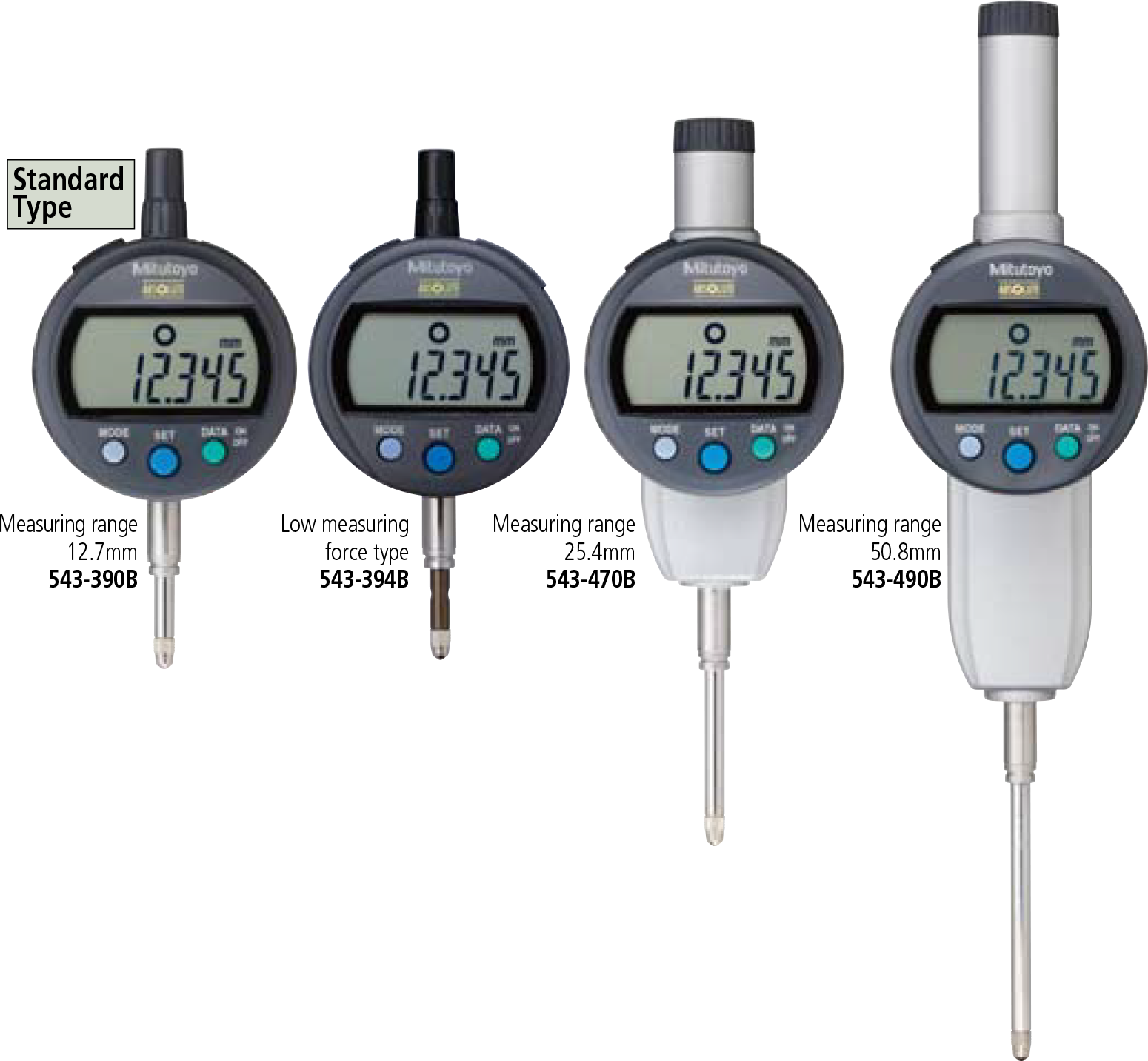
| 543-390 | 543-390B | 12.7mm |
0.001mm |
0.003mm | 1.5N or less | — |
| 543-394 | 543-394B | 0.4N – 0.7N | Low measuring force | |||
| — | 543-470B | 25.4mm | 1.8N or less | — | ||
| — | 543-490B | 50.8mm | 0.005mm | 2.3N or less | — | |
| 543-400 | 543-400B | 12.7mm |
0.01mm |
0.02mm | 0.9N or less | — |
| 543-404 | 543-404B | 0.2N – 0.5N | Low measuring force | |||
| — | 543-474B | 25.4mm | 1.8N or less | — | ||
| — | 543-494B | 50.8mm | 0.04mm | 2.3N or less | — | |
* Hysteresis: 0.001mm/0.01mm Resolution Type: 0.002mm
0.01mm Resolution Type: 0.02mm
* Repeatability: 0.001mm/0.01mm Resolution Type: 0.002mm
0.01mm Resolution Type: 0.02mm
Inch/Metric
| Order No. (w/ lug, flat-back) | Range | Resolution | Overall accuracy* | Measuring force | Remarks | |
|---|---|---|---|---|---|---|
| 543-391 | 543-391B |
.5” |
.0005″/ .0001″/ .00005″/ .001mm / 0.01mm |
.0001” |
1.5N or less | — |
| 543-392 | 543-392B | 1.5N or less | — | |||
| 543-395 | 543-395B | 0.4N – 0.7N | Low measuring force | |||
| 543-396 | 543-396B | 0.4N – 0.7N | Low measuring force | |||
| — | 543-471B | 1” | 1.8N or less** | — | ||
| — | 543-472B | 1.8N or less** | — | |||
| — | 543-491B | 2” | .0002” | 2.3N or less** | — | |
| — | 543-492B | 2.3N or less** | — | |||
| 543-401 | 543-401B |
.5” |
.0005”/0.01mm |
.001” |
0.9N or less | — |
| 543-402 | 543-402B | 0.9N or less | — | |||
| 543-405 | 543-405B | 0.2N – 0.5N | Low measuring force | |||
| 543-406 | 543-406B | 0.2N – 0.5N | Low measuring force | |||
| — | 543-475B | 1” | 1.8N or less** | — | ||
| — | 543-476B | 1.8N or less** | — | |||
| — | 543-495B | 2” | .0015” | 2.3N or less** | — | |
| — | 543-496B | 2.3N or less** | — | |||
* Hysteresis: .0005”/.0001”/.0005”/0.001mm/0.01mm
Resolution Type: .00010”/0.002mm
.0005”/0.01mm Resolution Type: .0010”/0.02mm
* Quantizing error of ±1 count is excluded
** Applies for a spindle orientation between the spindles
* Repeatability: .0005”/.0001”/.0005”/0.001mm/0.01mm
Resolution Type: .00010”/0.002mm
.0005”/0.01mm Resolution Type: .0005”/0.02mm
DIMENSIONS
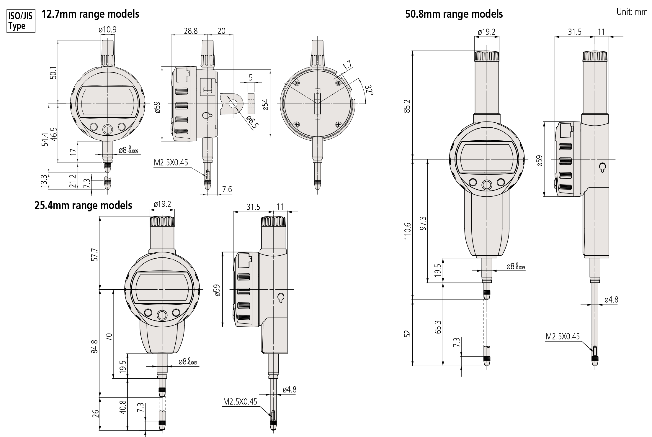
Note 1: Dimensions of the inch (ANSI/AGD Type) dial indicator partly differ from those of the metric (ISO/JIS Type) indicator.
Note 2: Inch (ANSI/AGD Type) dial indicators are provided with a stem of 3/8″ dia. and #4-48UNF thread mount for the contact point.
Note 3: Products with an Order No. suffixed “B” have a plain back, and other models have a center lug back.
Refer to page F-55 for details of the backs.
Technical Data
Accuracy: Refer to the list of specifications (excluding quantizing error)
Resolution:
0.01mm type 0.01mm
0.001mm type 0.01mm/0.001mm
.0005″/0.01mm type .0005″/0.01mm
.00005” /0.001mm type .0005 ”/.0001”/.00005 ” / 0.01mm/0.001mm
Display: 6-digit LCD and sign
Scale type: ABSOLUTE electrostatic linear encoder
Max. response speed: Unlimited (Measurement by scanning cannot be performed)
Measuring force: Refer to the list of specifications
Stem dia.: 8mm (ISO/JIS type) or 3/8”(ANSI/AGD type)
Battery: SR44 (1 pc.), 938882 for initial
operational checks (standard accessory)
Battery life: Approx. 7,000 hours of continuous use
Dust/Water protection level: IP42
Functions
Preset, Zeroset, GO/±NG judgment, Counting
direction switching, Power ON/OFF, Simplified calculation,
Function lock, Data hold, Data output,
inch/mm conversion (inch/mm models)
Alarm: Low voltage, Counting value composition error,
Overflow error, Tolerance limit setting error
Optional Accessories
•Lifting
Lifting lever:
No.21EZA198 (12.7mm/.5” ISO/JIS type)
No.21EZA199 (12.7mm/.5” ASME/ANSI/AGD type)
Lifting knob:
No.21EZA105 (12.7mm/.5” ISO/JIS type)*
No.21EZA150 (12.7mm/.5” ASME/ANSI/AGD type)*
No.21EZA197 (25.4mm/1” models)
No.21EZA200 (50.8mm/2” models)
Lifting cable: No.540774
Lifting lever: No.137693
(for measuring range: 25.4 and 50.8mm)
(supplied with 25.4mm and 50.8mm models as standard.)
• Auxiliary spindle spring:
No.02ACA571 (25.4mm/1” models)**
No.02ACA773 (50.8mm/2” models)**
• Lug-on-senter back:
No.101040 (25.4mm/1” and 50.8mm/2”, ISO/JIS type)
No.101306
(25.4mm/1” and 50.8mm/2”, ASME/ANSI/AGD type)
* Not available for low measuring force models.
**Required when orienting the indicator upside down.
• SPC Cable:
No.905338 (1m)
No.905409 (2m)
• USB Input Tool Direct (2m): 06ADV380F
• Connecting Cables for U-WAVE-T (160mm):
No.02AZD790F
For footswitch (02AZE140F)
Refer to page F-60 for details.
• Digimatic Mini-Processor DP-1VR: 264-504
• Contact points for Mitutoyo’s dial indicators (Refer to pages F-46 to F-49 for details.)
Interchangeable backs for 2 series (Refer to page F-50 for details.)
• Measuring stands (Refer to page F-80 for details.)
Setting measuring force on low measuring force models
• 543-404/404B/405/405B/406/406B
| Spindle orientation | Spring | Weight(approximately 0.1N) | Maximum measuring force |
|---|---|---|---|
|
Pointing vertically downward |
Yes | Yes | 0.5N or less |
| Yes | No | 0.4N or less | |
| No | Yes | 0.3N or less | |
| No | No | 0.2N or less | |
| Horizontal | Yes | No | 0.3N or less |
Note) Operation using configurations other than shown above is not guaranteed.
• 543-394/394B/395/395B/396/396B
| Spindle orientation | Spring | Weight(approximately 0.1N) | Maximum measuring force |
|---|---|---|---|
|
Pointing vertically downward |
Yes | Yes | 0.7N or less |
| Yes | No | 0.6N or less | |
| No | Yes | 0.4N or less | |
| No | No | Not guaranteed | |
| Horizontal | Not guaranteed | ||
Note) Operation using configurations other than shown above is
not guaranteed.
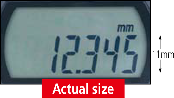
Large LCD
The large LCD incorporates 11mm characters giving 1.5 times the character area of conventional products (which
display 8.5mm characters) making measurement values much easier to read.
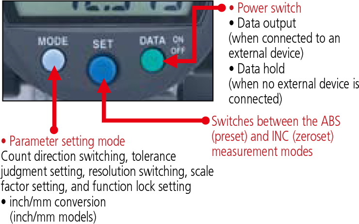
Three large buttons
The popular three-large button design, which is used in products such as the ABS coolant proof Digimatic indicators ID-N/B, makes buttons easier to press and operations easier to perform.
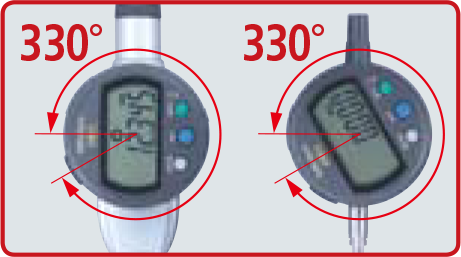
330º rotary display
The display can be rotated 330°, allowing use at a position where you can easily read the measurement value.
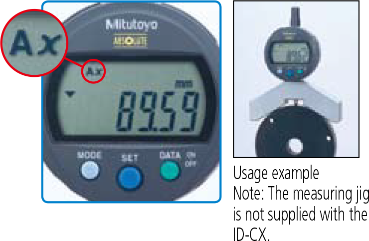
Calculation: f (x) = Ax
Mounting the ID-CX on a measuring jig and setting the multiplying factor (to any practical value) allows direct indicationof size (see example below) without using a conversion table and so improves measurement efficiency.
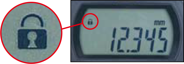
Function locking
Ensures reliability of measurement by locking the settings to prevent preset function settings from being changed by mistake.