Call Us: +91-7410524141
Call Us: +91-7410524141
SPECIFICATIONS
Metric
| Order No.* | Range | Resolution | Accuracy** |
|---|---|---|---|
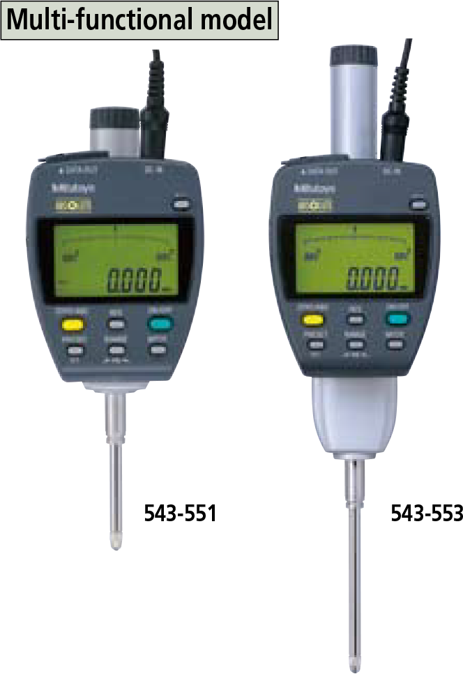
| 543-551 | 25mm |
0.001mm, 0.01mm |
0.003mm |
| 543-557 | 50mm | 0.003mm | |
| 543-553 | 50mm | 0.006mm |
* To denote your AC power cable add the following suffixes to the order No.: A for UL/CSA, D for CEE, DC for CCC, E for BS, K for KC, No suffix is required for JIS/100V
**Quantizing error of ±1 count is excluded.
Inch/Metric
| Order No.* | Range | Resolution | Accuracy** |
|---|---|---|---|
| 543-552 | 1” /
25.4mm |
.00005”, .0001”, .0005”, .001”, 0.001mm, 0.01mm |
.00012” /
0.003mm |
| 543-558 | 2” /
50.8mm |
.00012” /
0.003mm |
|
| 543-554 | 2” /
50.8mm |
.00024” /
0.006mm |
* To denote your AC power cable add the following suffixes to the order No.: A for UL/CSA, D for CEE, DC for CCC, E for BS, K for KC, No suffix is required for JIS/100V
**Quantizing error of ±1 count is excluded.
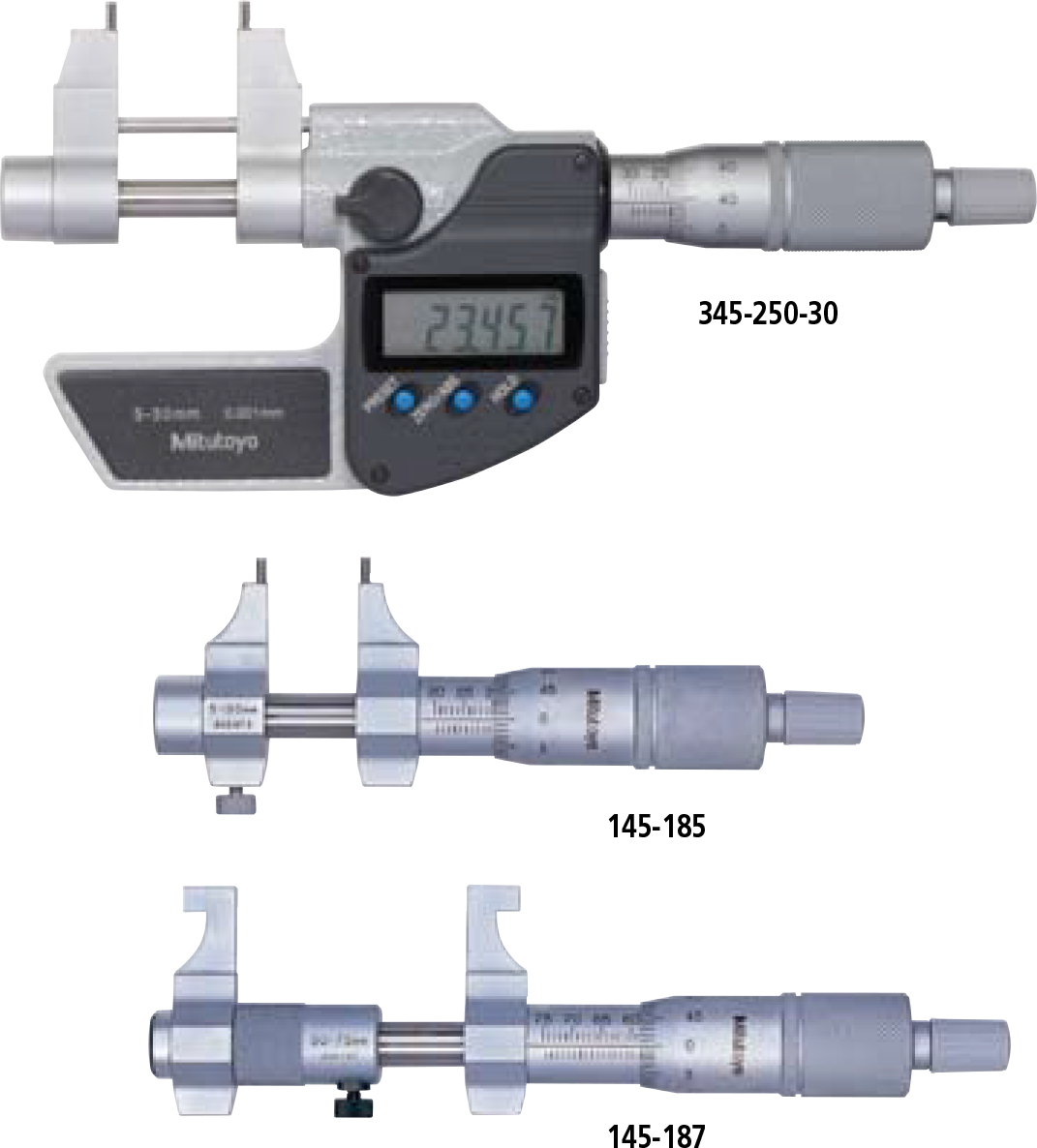
DIMENSIONS
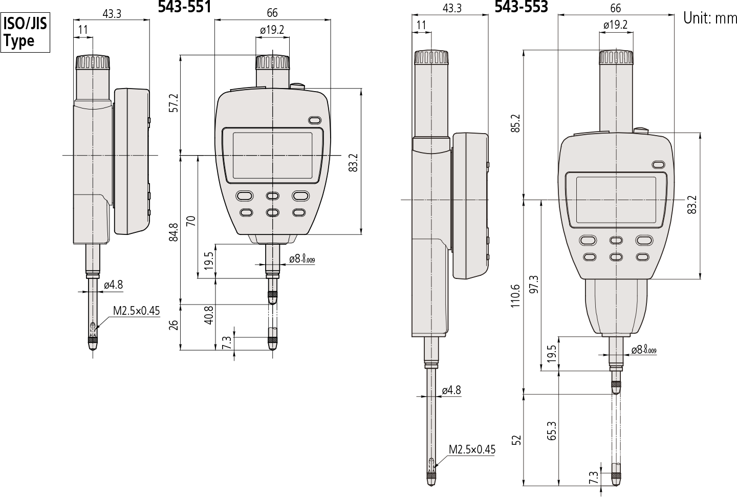
Note 1: Dimensions of the inch (ANSI/AGD Type) dial indicator partly differ from those of the metric (ISO/JIS Type) indicator.
Note 2: Inch (ANSI/AGD Type) dial indicators are provided with a stem of 3/8″ dia. and #4-48UNF thread mount for the contact point.
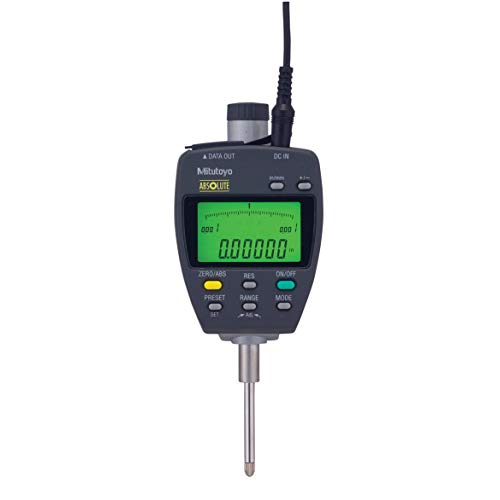
Technical Data
Resolution: 0.01mm/0.001mm or .00005”/.0001”/.0005
”/.001”/0.001mm/0.01mm
Display: 6-digit LCD, sign, and analog bar with 2-color
backlight
Scale type: ABSOLUTE electrostatic linear encoder
Max. response speed: Unlimited
Measuring force: 1.8N or less (25.4mm models)
2.3N or less (50.8mm models)
Spindle orientation: Between the spindle pointing vertically
downward to the spindle horizontal
Stem dia.: 8mm (ISO/JIS type) or 3/8” (ANSI/AGD type)
Power supply: 9V DC (via AC adaptor) 06AEG302
Lifting lever: 137693
* To denote your AC power cable add the following
suffixes to the order No.: A for UL/CSA, D for CEE, DC
for CCC, E for BS, K for KC, No suffix is required for
JIS/100V
Functions
Preset, Zeroset, GO/±NG judgment, Max/Min value hold,
Runout measurement, Resolution switching,
Counting direction switching, Power ON/OFF, Data output,
inch/mm conversion (inch/mm models)
Alarm: Counting value composition error, Overflow
error, Tolerance limit setting error
Optional Accessories
• Lifting cable: No.540774 (stroke 25.4mm)
• Auxiliary spindle spring:
No.02ACA571 (25.4mm/1” models)*
No.02ACA773 (50.8mm/2” models)*
• Lug-on-center back:
No.101040 (ISO/JIS type)
No.101306 (ASME/ANSI/AGD type)
* Required when orienting the indicator upside down.
• SPC cable:
No.936937 (1m)
No.965014 (2m)
• USB Input Tool Direct (2m) : No.06ADV380F
• Connecting Cables for U-WAVE-T (160mm) :
No.02AZD790D
For footswitch: No.02AZE140D
Refer to page F-60 for details.
• Digimatic Mini-Processor DP-1VR: 264-504
• Contact points for Mitutoyo’s dial indicators *
• Interchangeable backs for Series 2 models*
• Measuring stands
* 4 Refer to pages F-46 to F-49 for details.
* 5 Refer to page F-50 for details.
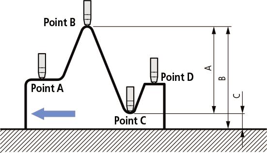
Application
Difference/Runout measurement
Example: Indicator travel from points A to D
Difference (or Total Runout) is displayed as A. Dimensions B (maximum value) and C (minimum value) can be recalled from memory with a simple key sequence.