Call Us: +91-7410524141
Call Us: +91-7410524141
SPECIFICATIONS
Metric
| Order No. (w/ lug, flat-back) | Range | Resolution | Accuracy*2 | Measuring force | |
|---|---|---|---|---|---|
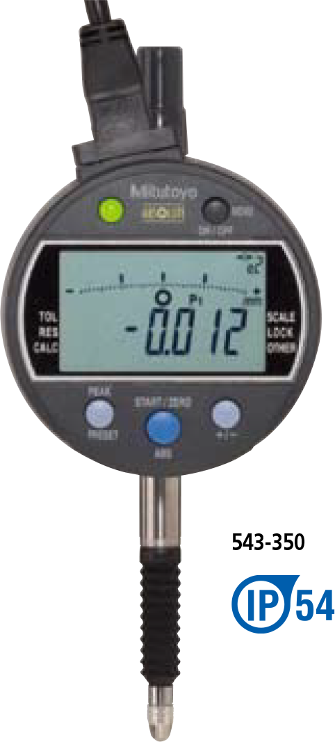
| 543-350 | 543-350B | 12.7mm | 0.001/0.01mm | 0.003mm or less | 2.5N or less |
Inch/Metric
| Order No. (w/ lug, flat-back) | Range | Resolution | Accuracy*2 | Measuring force | |
|---|---|---|---|---|---|
| 543-351 | 543-351B | .5” / 12.7mm | .00005/.0001/.0005” //
0.001/0.01mm |
±.00010” / 0.003mm or less | 2.5N or less |
| 543-352 | 543-352B | ||||
Notes:
1) LCD readout does not rotate.
2) Max./min. holding: sample rate is 100 readings/sec; max. rate of change of reading is 100μm/sec.
3) Products with an Order No. suffixed “B” have a flat back
4) Standard contact point: 901312 (ISO/JIS type), 21BZB005 (ANSI/AGD type)
*2 Quantizing error of ±1 count is excluded.
DIMENSIONS
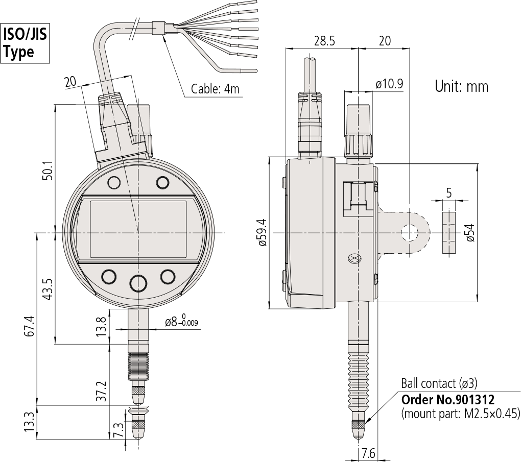
Note 1: Dimensions of the inch (ANSI/AGD Type) dial indicator partly differ from those of the metric (ISO/JIS Type) indicator.
Note 2: Inch (ANSI/AGD Type) dial indicators are provided with a stem of 3/8″ dia. and #4-48UNF thread mount for the contact point.
Functions
Signal output (–NG/OK/+NG, N-ch open drain, logical invert is available), Remote control (peak start preset/zero-set),Preset, Zeroset, GO/±NG judgment (3 pairs of ABS, INC memory function) Max/Min/Runout value holding, Measurement direction switching, Power ON/OFF, inch/mm conversion (inch/mm models), Resolution switching, Scaling function f(x)=Ax, Key lock, Calibration mode (Signal output in Digimatic code format).
Alarm: Counting value composition error, Overflow error, Tolerance limit setting error
Optional accessories
• Lifting* 3
Lifting lever No.21EZA198 (ISO/JIS/DIN Type),
No.21EZA199 (ASME/ANSI/ AGD Type)
Lifting knob No.21EZA105 (ISO/JIS/DIN Type),
No.21EZA150 (ASME/ANSI/ AGD Type)
Lifting cable No.540774
• Digimatic power unit: 21EZA345
Note: To denote your AC power cable add the following
suffixes to the order No.: A for UL/CSA, D for
CEE, DC for CCC, E for KC. No suffix is required
for JIS/100VAC.
Used in the calibration mode when executing
automatic inspection using i-Checker.
In such a case, please purchase connecting cable
21EAA194 (1m), or 21EAA190 (2m).
• Contact points for Mitutoyo’s dial indicators.*
• Interchangeable backs for Series 2 models. Dust-water
protection is not guaranteed. Use the waterproof types
of Series 2 for plain backs if required.*5
• Measuring stands (Refer to page F-75 to F-80 for details.
*3 Dust-water protection is not guaranteed.
*4 Refer to pages F-46 to F-49 for details.
*5 Refer to page F-50 for details.
Output signals and LCD display
| Wire | – NG | OK | + NG | Composition error |
|---|---|---|---|---|
| Orange (– NG) | Low | High | High | High |
| Green (OK) | High | Low | High | High |
| Brown (+ NG) | High | High | Low | High |
| LCD | “x.xxE” indication |
* Logical invert is available.
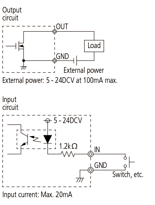
I/O Specifications
| Wire | Signal | I/O | Description |
|---|---|---|---|
| Black | – V (GND) | — | Connected to minus (-)
terminal |
| Red | + V | — | Power supply (5 – 24VDC) |
| Orange | – NG | O | Tolerance judgment
result output: Only the terminal corresponding to a judgment result is set to the low level. |
| Green | OK | O | |
| Brown | + NG | O | |
| Yellow | PRESET_RECALL
ZERO |
I | External input terminal: If
the relevant terminal is set to the low level, its signal becomes true. |
| Blue | PEAK_START | I | |
| Shield | FG | — | Connected to GND (Earth) |
Note: Measurement data cannot be output.