Call Us: +91-7972969901
Call Us: +91-7972969901

Metric
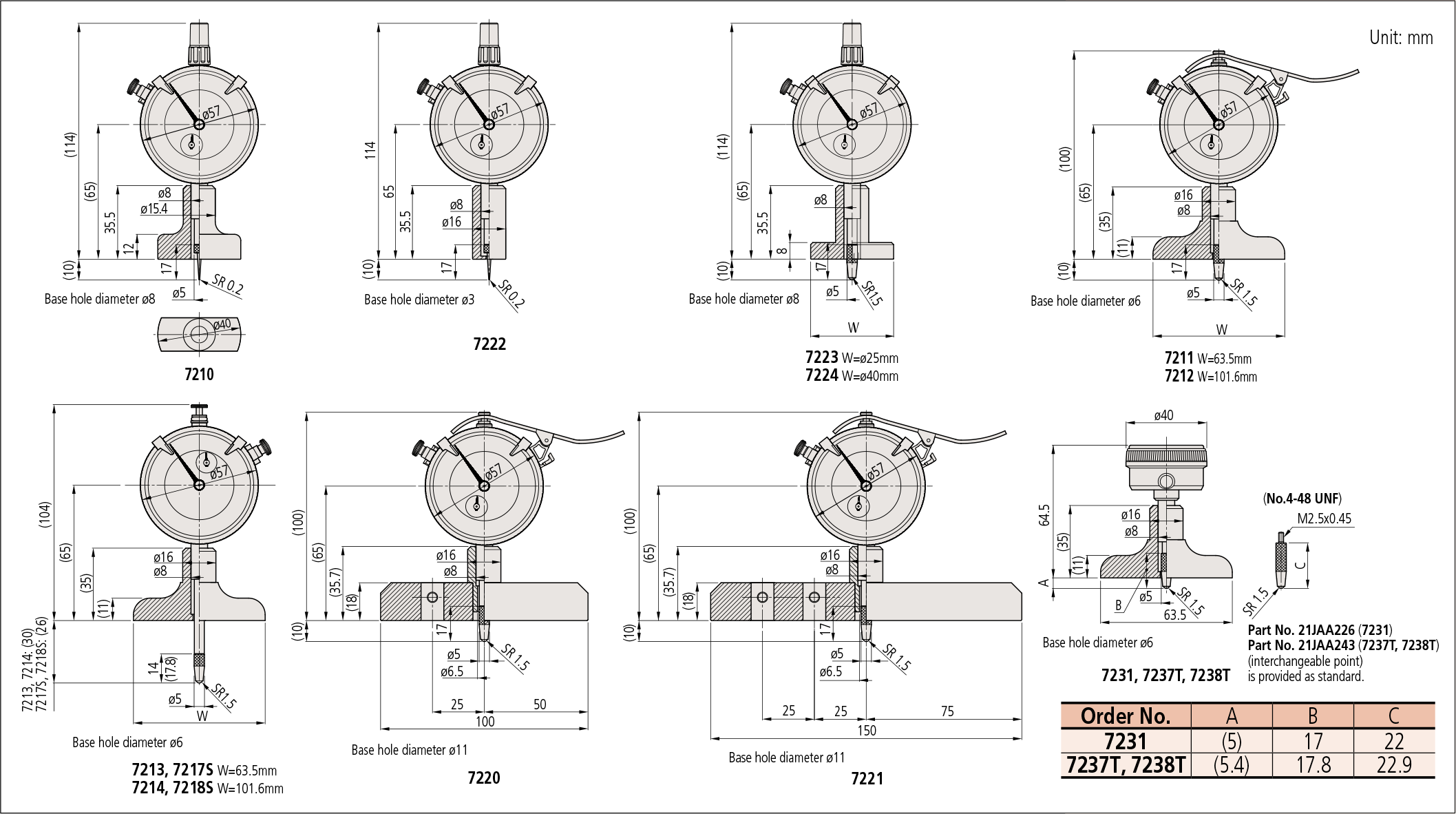
| Order No. | Range | Graduation | Accuracy | Stroke | Measuring force | Contact point*1 | Extension rod*2 | Indicator*3 (dial indicator) | ||||
|---|---|---|---|---|---|---|---|---|---|---|---|---|
| W | T | Flatness | Mounting position of a dial indicator | |||||||||
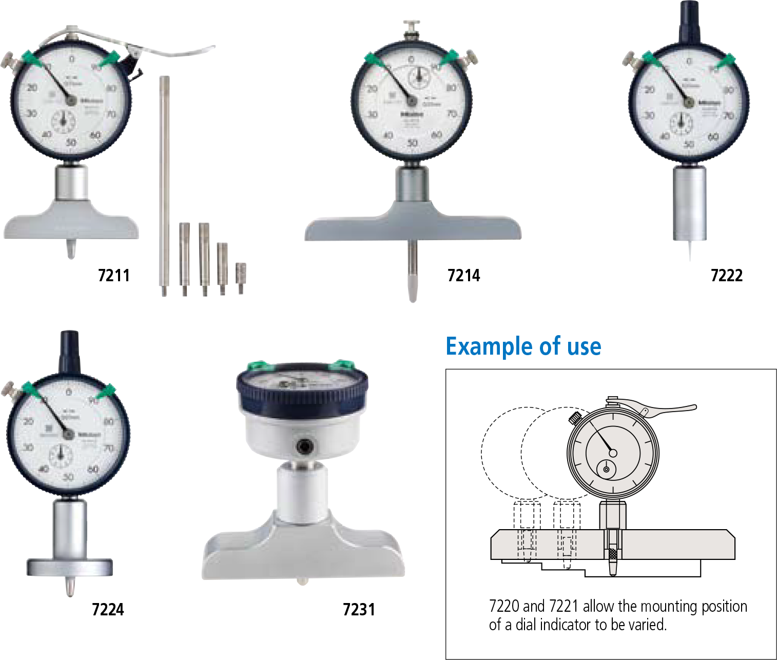
| 7210 | 0 – 10mm |
0.01mm |
±15μm |
10mm |
1.4N |
40mm |
16mm |
5μm |
1 |
Provided with a needle
point (No.137413) |
— |
2902SB for Depth Gage |
| 7211 | 0 – 200mm | 63.5mm | Provided with a carbide- tipped ball point
(No.21JAA224) |
5 pcs. (10, 20, 30, 30, 100mm) | ||||||||
| 7212 | 101.6mm | |||||||||||
| 7213 | 0 – 210mm | ±30μm | 30mm | 2.5N | 63.5mm | Provided with a carbide- tipped ball point
(No.21JAA225) |
3 pcs. (30, 60, 90mm) | 2952SB
for Depth Gage |
||||
| 7214 | 101.6mm | |||||||||||
| 7220 |
0 – 200mm |
±15μm |
10mm |
1.4N |
100mm |
18mm |
2 | Provided with a carbide- tipped ball point (No.21JAA224) | 5 pcs. (10, 20, 30, 30, 100mm) |
2902SB for Depth Gage |
||
| 7221 | 150mm | 3 | ||||||||||
| 7222 |
0 – 10mm |
ø16mm |
1 |
Provided with a needle
point (No.137413) |
— |
|||||||
| 7223 | ø25mm | Provided with a carbide- tipped ball point (No.21JAA224: 17mm) (No.21JAA226: 22mm) | ||||||||||
| 7224 | ø40mm | |||||||||||
| 7231 | 0 – 200mm | 5mm | 63.5mm | 16mm | 5 pcs. (10, 20, 30, 30, 100mm) | 1162T
for Depth Gage (Back plunger type) |
||||||
Inch
| Order No. | Range | Graduation | Accuracy | Stroke | Measuring force | Contact point*1 | Extension rod*2 | Indicator*3 (dial indicator) | ||||
|---|---|---|---|---|---|---|---|---|---|---|---|---|
| W | T | Flatness | Mounting position of a dial indicator | |||||||||
| 7217S |
0 – 8” |
.001” |
±.002” |
1” | 2.5N | 63.5mm |
16mm |
.0002″ |
1 |
Carbide ball point (No.21JZA242) | 3 pcs. (1”, 2”, 4”) | 2904SB
for Depth Gage |
| 7218S | 101.6mm | |||||||||||
| 7237T |
.2” |
1.4N |
63.5mm | Provided with a carbide- tipped ball point (No.21JZA242: 17.8mm) (No.21JZA243: 22.9mm) |
4 pcs. (.5”, 1”, 2”, 4”) |
1168T
for Depth Gage (Back plunger type) |
||||||
| 7238T | 101.6mm | |||||||||||
DIMENSIONS
Note:
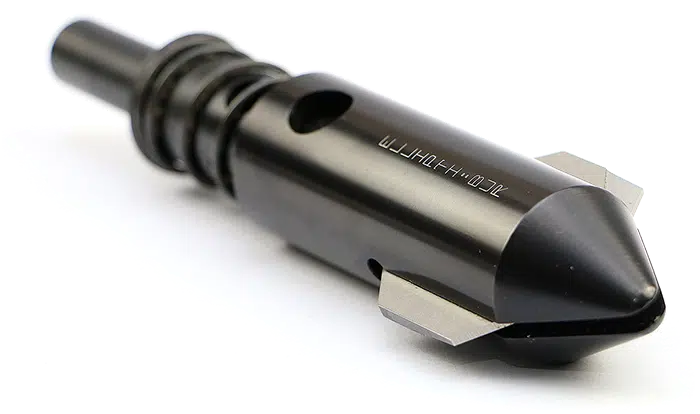
*1
Caution should be exercised when exchanging a contact point of a Depth Gage (Dial/Digimatic Indicator)
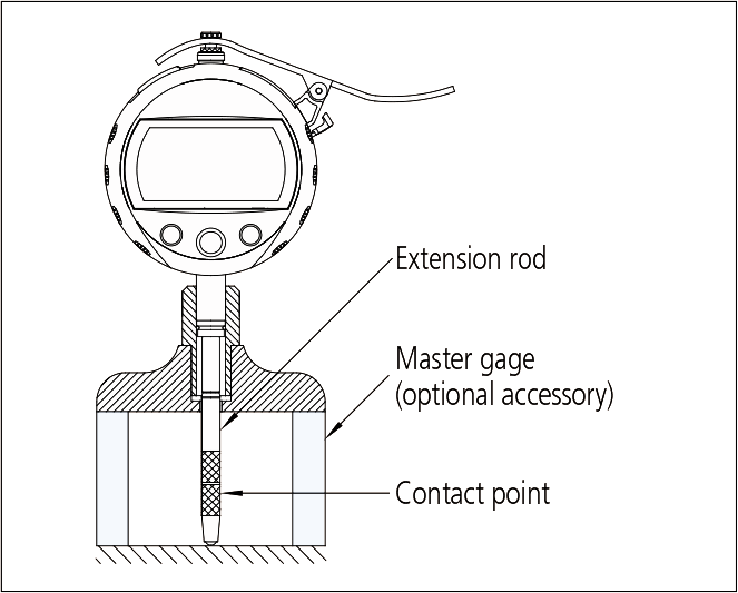
*2
Caution on should be exercised when using an extension rod
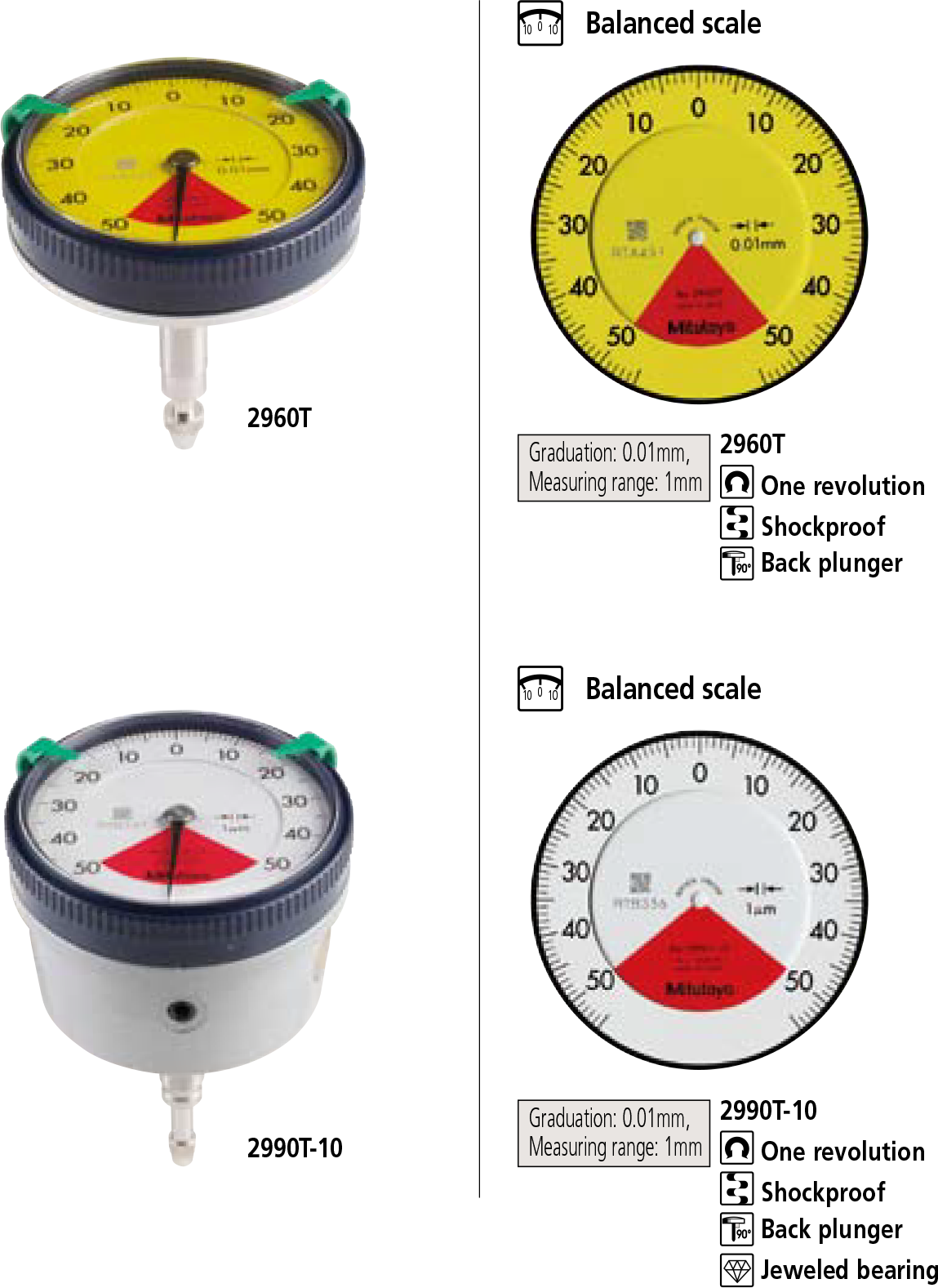
*3
Indicators