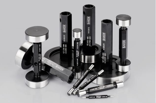
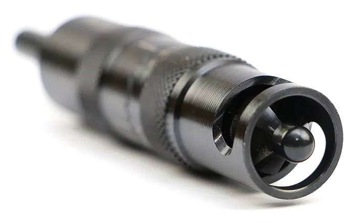
Air Plug Gauge: Range 1.5 – 250 mm FEATURES: Quick and easy checking of bore Standard 2 jets for checking size, taper, ovality 3 jets at 120 degree for average size & tri-lobed effect (for diameter 6 mm & above) With extensions to check deeper bores Can be supplied to check through or blind bores
3 jets at 120 degree for average size & tri-lobed effect (for diameter 6 mm & above)
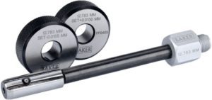
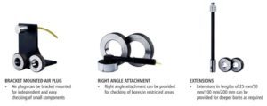
With extensions to check deeper bores
Can be supplied to check through or blind bores
Can be supplied with multiple jets
Hard chrome plated for extended life
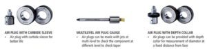
Can be supplied with carbide sleeve on request
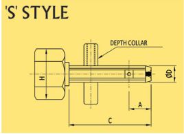
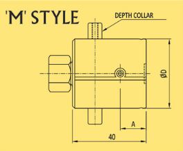
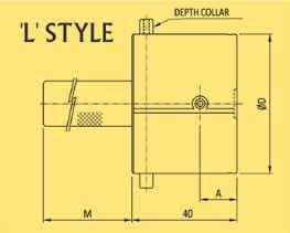
For specific depth or land width checking, adjustable depth collars can be provided
Special Application
Data Sheet
Ø D mm
A
C
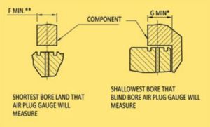
F**
G*
H
MIN RANGE
MAX RANGE
THROUGH
BLIND
THROUGH
BLIND
1.5-3.0 #
4
–
12
–
2.5
–
7
±0.005
±0.015
3.0-4.0
6.5
3
24
20.5
2.5
4
18.5
±0.005
±0.015
4.0-6.0
9
3
31
25
2.5
4
18.5
±0.005
±0.015
Ø 1.5 to 3 mm air plugs are not supplied with extensions and are supplied in hand held design only with PVC tubing
For deeper holes, use extensions which increase by 25 & 50 mm (above Ø 3 mm only)
Ø 1.5 to 6 mm air plug gauges are supplied on MOD-2A and ClearLine ±0.025 mm unit
# not supplied in blind bore design
Ø D mm
A
F** MOD1A/CL
G* MOD1A/CL
MIN RANGE
MAX RANGE
THROUGH
BLIND
6.0-13.0
15.0
4.0
4.5/3.5
6.5/6.0
±0.005
±0.030
13.0-20.0
15.0
4.5
4.5/3.5
6.5/6.0
±0.005
±0.030
20.0-35.0
15.0
4.5
4.5/3.5
6.5/6.0
±0.005
±0.030
35.0-60.0
15.0
4.5
4.5/3.5
6.5/6.0
±0.005
±0.030
For deeper holes, use extensions which increase by 50, 100, 200 and 300 mm
Quick entry pilot is provided for air plug gauges above 13 as a standard (others on request)
As a special case, air plug gauges can be supplied on MOD 2A unit up to Ø 50 mm only to suit super blind or for less land. Maximum range for this will be ±0.020 mm only (others on request)
Ø D mm
A
F** MOD1A/CL
G* MOD1A/CL
M
MIN RANGE
MAX RANGE
THROUGH
BLIND
60.0-100.0
15.0
4.5
4.5/3.5
6.5/6.0
100.00
±0.005
±0.030
100.0-150.0#
15.0
4.5
4.5/3.5
6.5/6.0
150.00
±0.010
±0.030
150.0-200.0#
15.0
4.5
4.5/3.5
6.5/6.0
200.00
±0.015
±0.060
Supplied hand held as standard for PFL MOD-1A only
For deeper holes, extended “M” can be provided
# not supplied for use on ±0.025 mm ClearLine unit and MOD-2A
Above 200 mm and up to 250 mm on request
General Notes
Air plug gauge for 0.0005 mm least count are given up to Ø 50 mm only
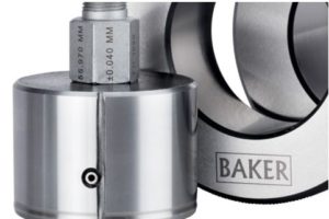
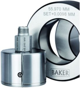
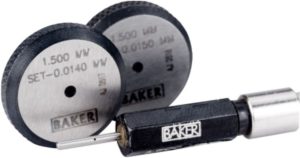
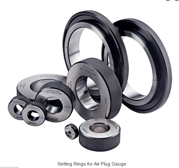
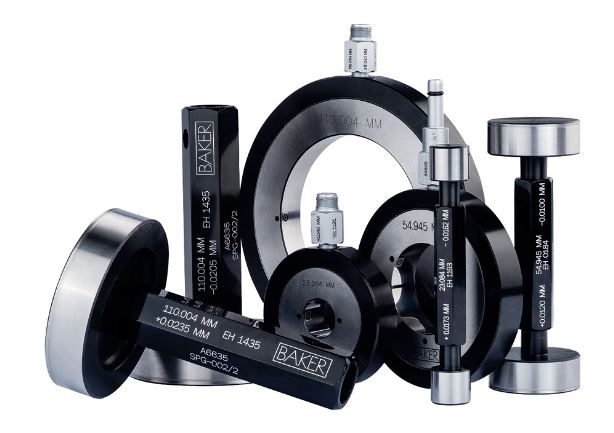
Each air plug gauge requires two setting rings to set the air plug on the read out unit. The difference between the high and low setting rings supplied covers the component tolerance or the maximum range mentioned in the above table whichever is lower
Depth collar is supplied against order for positioning air plug gauge jets to fixed depth
The minimum bore land “F” and “G” mentioned, is excluding chamfer distance and fillet radius
For special blind bore air plugs (super blind – G less than mentioned in the above chart) or any other special requirement (3 jet or 5 jet design to check lobing), please send the component drawing and ask for a quote
Abbreviations
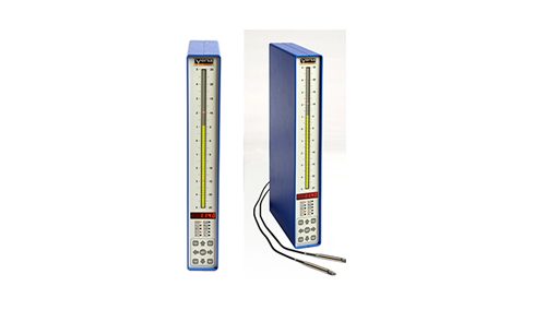
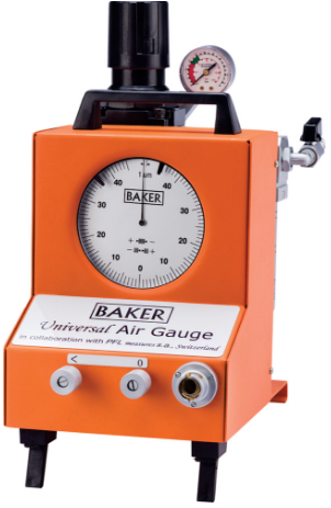
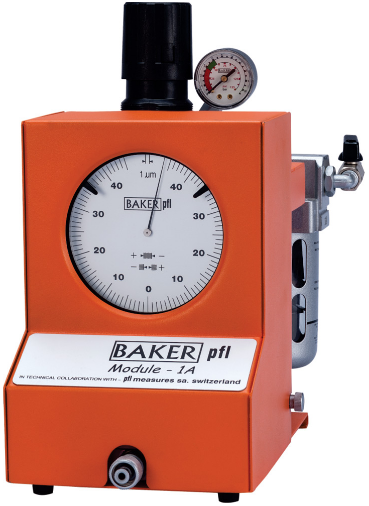
MOD 1A = PFL Air Gauge Unit Module 1A
MOD 2A = PFL Air Gauge Unit Module 2A
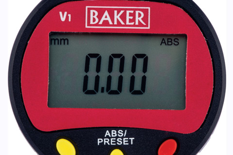
CL = ClearLine air gauge unit
Important rule in air gauging
Lesser the clearance, higher the accuracy and vice versa