Call Us: +91-7410524141
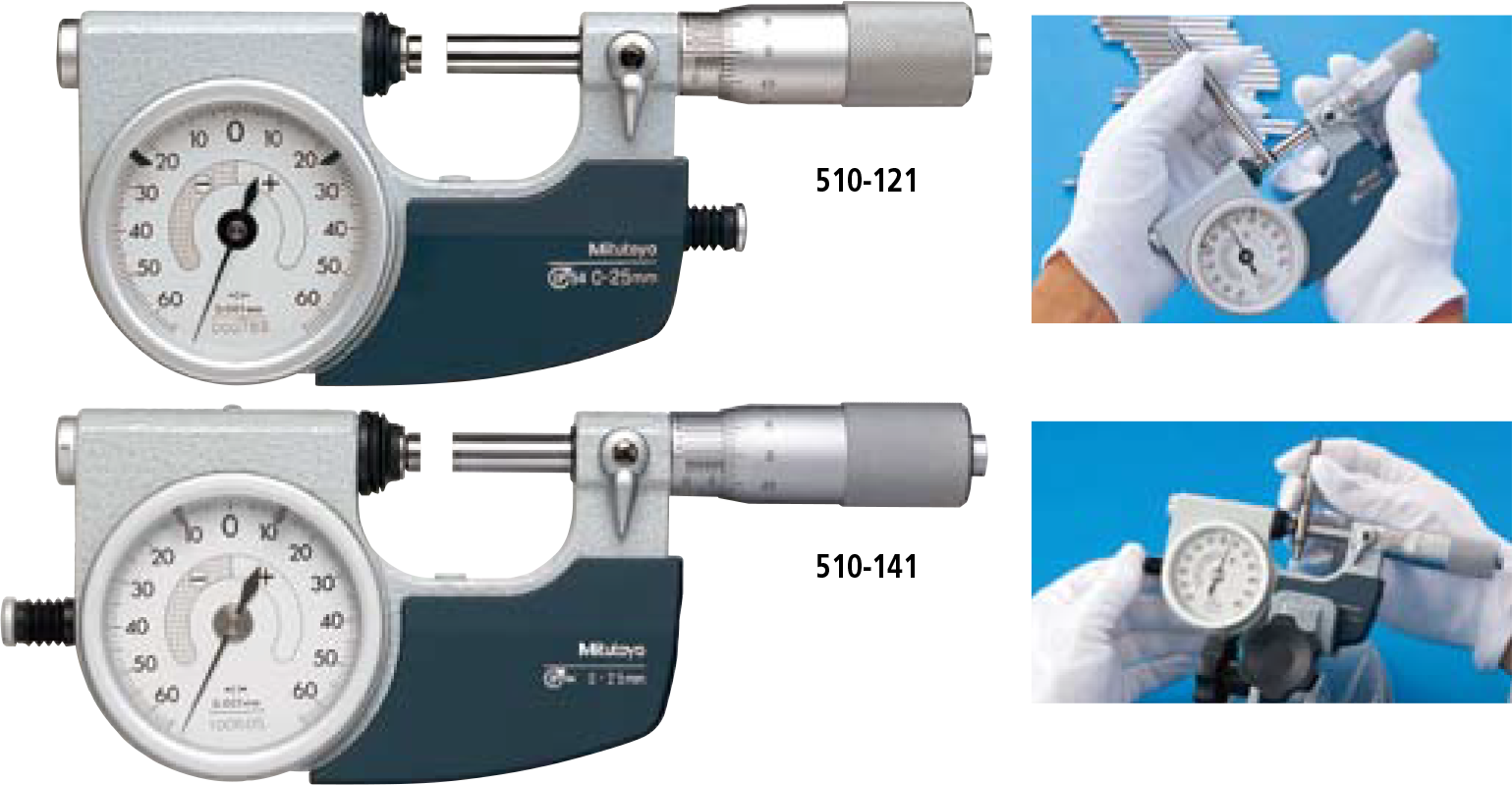
MITUTOYO-SERIES 510-INDICATING MICROMETERS
Suited to the measurement of low-volume manufactured parts. Easy to use when operating one-handed due to retractable anvil. In the 25mm measuring range, the model lineup offers a choice of left or right positioning of the anvil-retraction button. Greatly improved accuracy: indication error and graduation of 1μm. Water-proof to protection level IP54. Hard-coated crystal: enhanced oil andSPECIFICATIONS
Metric
| Order No. | Range | Indicating range | Graduation | Dial graduation | Measuring force | Anvil retraction button | Mass |
|---|---|---|---|---|---|---|---|
| 510-121 | 0 – 25mm |
±0.06mm |
0.001mm |
0.001mm |
5 – 10N |
Right side | 520g |
| 510-141 |
Left side |
530g | |||||
| 510-122 | 25 – 50mm | 670g | |||||
| 510-123 | 50 – 75mm | 820g | |||||
| 510-124 | 75 – 100mm | 970g |
Inch
| Order No. | Range | Indicating range | Graduation | Dial graduation | Measuring force | Anvil retraction button | Mass |
|---|---|---|---|---|---|---|---|
| 510-131 | 0 – 1″ |
±.0023″ |
.0001″ |
.00005″ |
5 – 10N |
Right side | 520g |
| 510-151 |
Left side |
530g | |||||
| 510-132 | 1″ – 2″ | 670g | |||||
| 510-133 | 2″ – 3″ | 820g | |||||
| 510-134 | 3″ – 4″ | 970g |
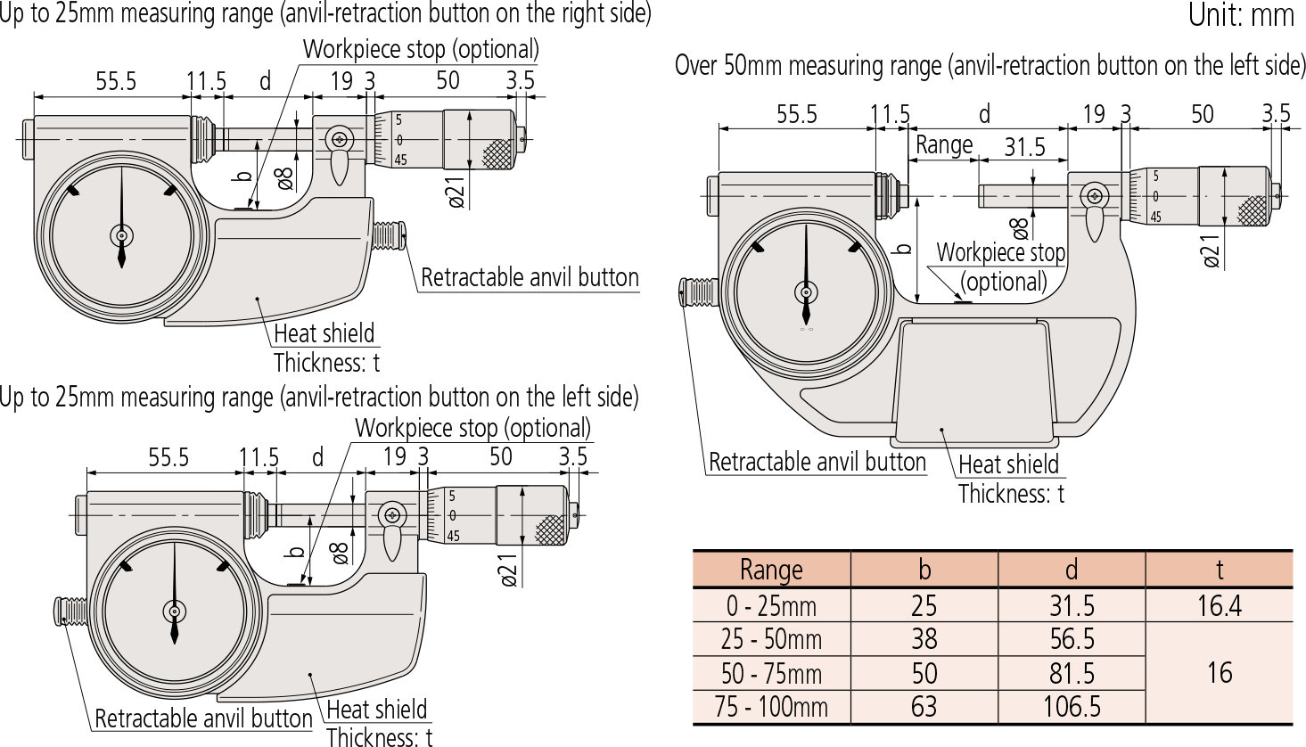
DIMENSIONS
Technical Data
Flatness: 0.3μm/.000012”
Parallelism: 0.6μm/ .000024” for models up to 50mm/ 2”
1μm/ .00004” for models over 50mm/ 2”
Accuracy: ±2μm
Spindle feed error: 3μm/ .00015”
Dispersion of indication: 0.4μm/ .00002”
Dial indication accuracy: 1μm/ .00005”
Standard accessories: Reference bar, 1 pc (except for measuring range 0-25mm (0-1″) models) Spanner (200154), 1 pc
Workpiece stop (optional)
Realizes more stable measurement.
Three types are available to suit workpieces of different sizes.
| Range | A | B |
|---|---|---|
| Workpiece stop A
04AZA124 |
016 | 23 |
| Workpiece stop B
04AZA125 |
014 | 20.5 |
| Workpiece stop C
04AZA126 |
014 | 15 |
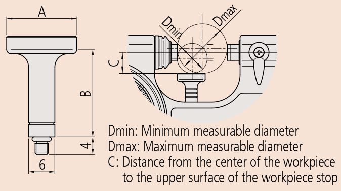
Order No 510-121, 510-141, 510-131, 510-151
| Dmin | Dmax | C | |
|---|---|---|---|
| Workpiece stop A | N/A | N/A | N/A |
| Workpiece stop B | 4 | 16 | 5.0 |
| Workpiece stop C | 15 | 25 | 10.5 |
510-122 and 510-132
| Dmin | Dmax | C | |
|---|---|---|---|
| Workpiece stop A | 25 | 37 | 15.5 |
| Workpiece stop B | 30 | 42 | 18.0 |
| Workpiece stop C | 41 | 50 | 23.5 |
510-123 and 510-133
| Dmin | Dmax | C | |
|---|---|---|---|
| Workpiece stop A | 50 | 61 | 27.5 |
| Workpiece stop B | 54 | 66 | 30.0 |
| Workpiece stop C | 65 | 75 | 35.5 |
510-124 and 510-134
| Dmin | Dmax | C | |
|---|---|---|---|
| Workpiece stop A | 75 | 87 | 40.5 |
| Workpiece stop B | 80 | 92 | 43.0 |
| Workpiece stop C | 91 | 100 | 48.2 |
- Suited to the measurement of low-volume manufactured parts.
- Easy to use when operating one-handed due to retractable anvil.
- In the 25mm measuring range, the model lineup offers a choice of left or right positioning of the anvil-retraction button.
- Greatly improved accuracy: indication error and graduation of 1μm.
- Water-proof to protection level IP54.
- Hard-coated crystal: enhanced oil and scratch resistance.
- Indicator scale is large and easy-to-read.
- The zero position and adjustable limit markers, for GO/±NG testing, are easily set.
- Measuring faces: Carbide


