Call Us: +91-7972969901
Call Us: +91-7972969901

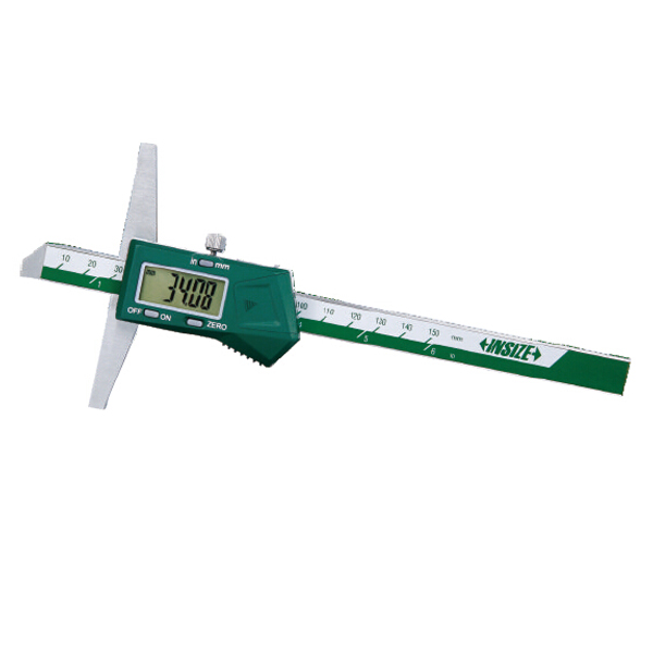
SPECIFICATIONS
Metric
| Order No. | Range | Resolution | Accuracy* | Remarks |
|---|---|---|---|---|
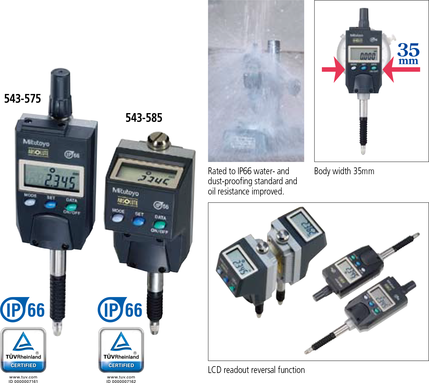
| 543-570 | 12.7mm | 0.01mm | 0.02mm | Slim type ID-N |
| 543-580 | 5.0mm | Back plunger type ID-B | ||
| 543-575 | 12.7mm | 0.01mm / 0.001mm | 0.01mm / 0.003mm | Slim type ID-N |
| 543-585 | 5.0mm | Back plunger type ID-B |
Inch/Metric
| Order No. | Range | Resolution | Accuracy* | Remarks |
|---|---|---|---|---|
| 543-571 | .5” | .0005”, 0.01mm | .001” | Slim type ID-N |
| 543-581 | .2” | Back plunger type ID-B | ||
| 543-576 | .5” | 0.01mm / 0.001mm
.0005” / .00005” |
.00012” | Slim type ID-N |
| 543-586 | .2” | Back plunger type ID-B |
*Quantizing error of ±1 count is excluded
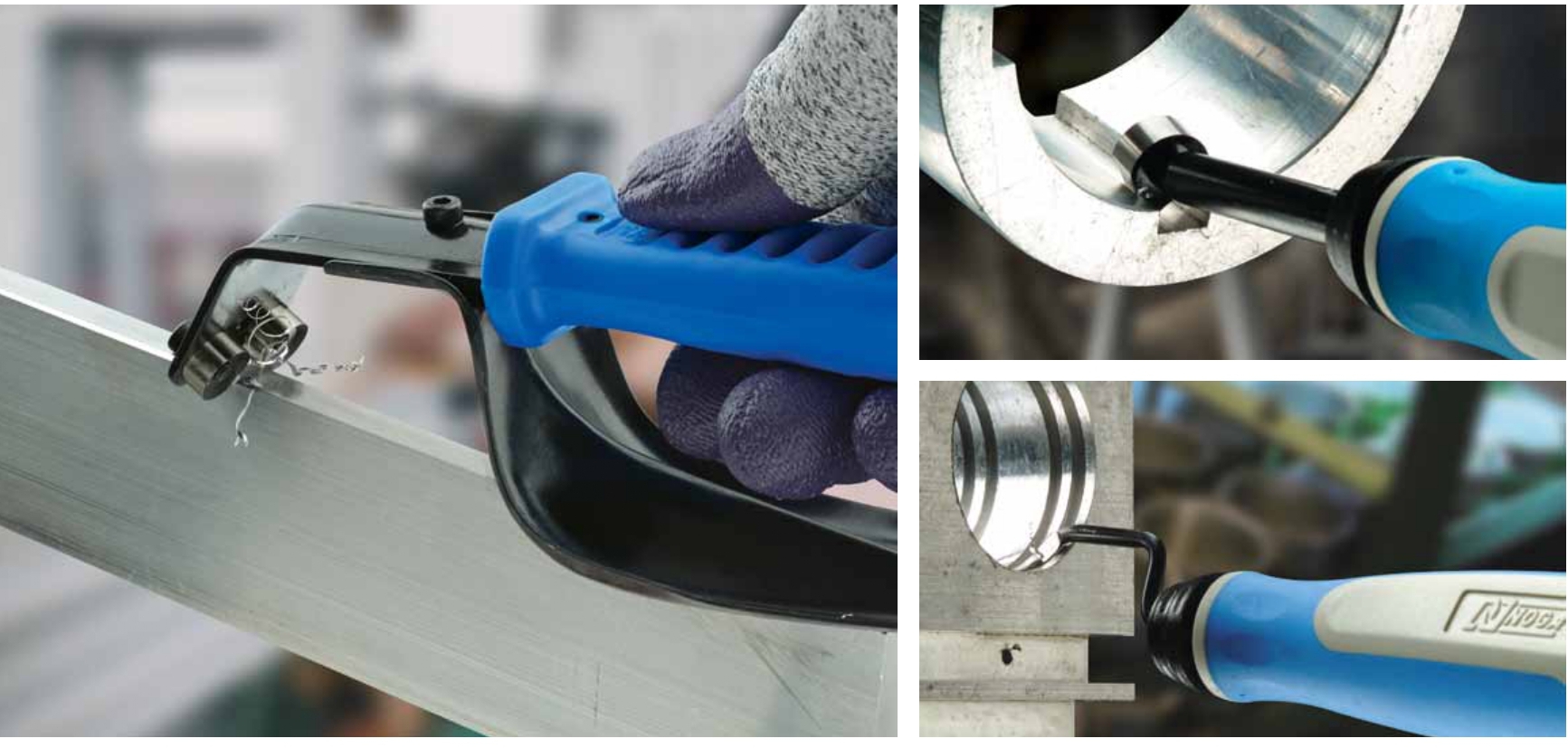
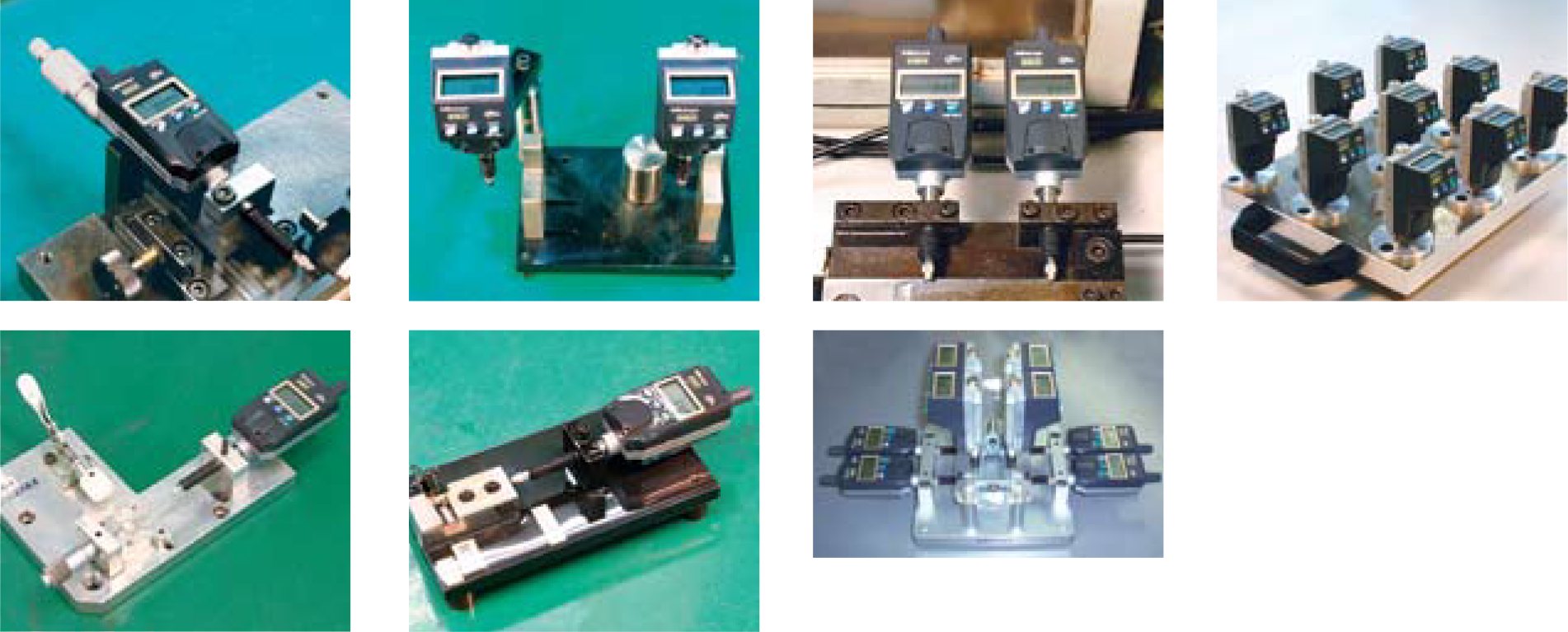
Usage examples
DIMENSIONS
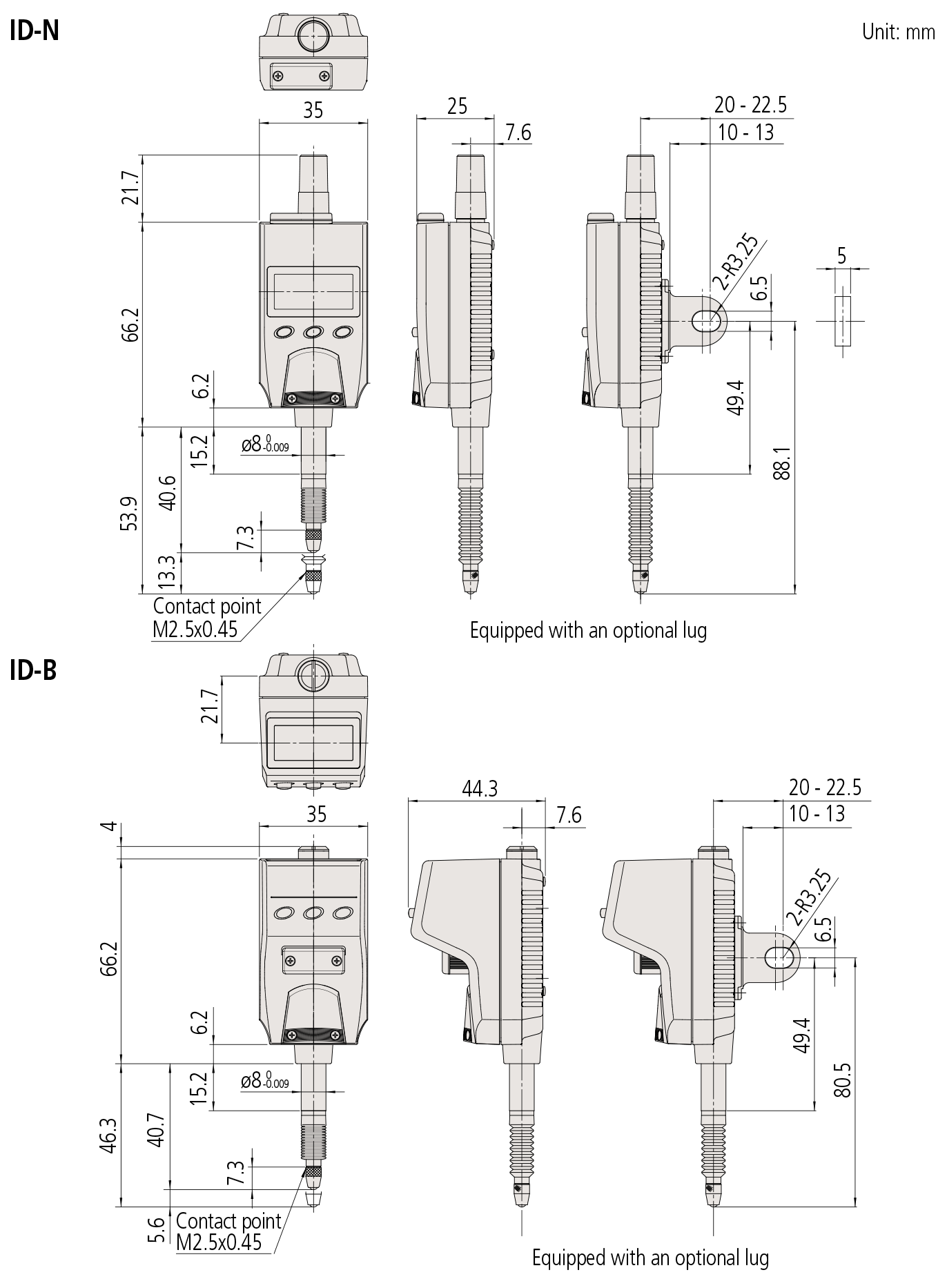
Note 1: Dimensions of the inch (ANSI/AGD Type) dial indicator partly differ from those of the metric (ISO/JIS Type) indicator.
Note 2: Inch (ANSI/AGD Type) dial indicators are provided with a stem of 3/8″ dia. and #4-48UNF thread mount for the contact point.
Technical Data
Display: 6-digit LCD and sign
Scale type: ABSOLUTE electrostatic linear encoder
Max. response speed: Unlimited (Measurement by scanning
cannot be performed)
Measuring force: 2.5N or less (ID-N)
2.0N or less (ID-B)
Stem dia: 8mm (ISO/JIS type) or 3/8″ (ANSI/AGD type)
Standard contact point: 901312 (ISO/JIS type)
21BZB005 (ANSI/AGD type)
Battery SR44 (1pc.) : 938882 for initial
operational checks (standard accessory)
Battery life: Approx. 7,000 hours of continuous use Functions
Zero-setting, Presetting, Direction switching, Tolerance
judgment, Display hold, Data output,
inch/mm conversion (inch/mm models), LCD readout reversal
Alarm: Low voltage, Counting value composition error,
Overflow error, Tolerance limit setting error
Optional accessories
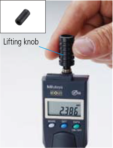
• Lifting knob (only for ID-N)
No.21EZA105 (ISO/JIS type)*
No.21EZA150 (ASME/ANSI/AGD type)*
Spindle can be manually lifted. Remove the spindle cap for
ID-N and attach the lifting knob to the spindle. Note that
water resistance is not maintained in this configuration.
Using the lifting knob
• Lug
No.21EZA145 (ISO/JIS type)
No.21EZA146 (ASME/ANSI/AGD type)
• Arm for ID-B (mode-to-order)
• Rubber boot
For oil resistance (NBR) No.02ACA376 (for ID-N)
No.125317 (for ID-B)
For durability (silicon) No.238774 (for ID-N)
No.21EAA212 (for ID-B)
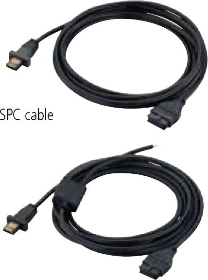
• SPC cable:
No.21EAA194 (1m)
No.21EAA190 (2m)
• USB Input Tool Direct (2m): No.06ADV380G
• Connecting Cables for U-WAVE-T (160mm) : No.02AZD790G
For footswitch: No.02AZE140G
Refer to page F-60 for details.
• Bifurcated connecting cable with zero-setting terminal:
No.21EAA210 (1m)
No.21EAA211 (2m)
Two of the wires inside the cable are separated for zero setting without touching the SET switch on the main body.
Use these cables in combination with commercially available switches. Zero setting is performed by briefly connecting these two wires together (less than a second), and ABS preset & recall by connecting for a second or more.
• Contact points for Mitutoyo’s dial indicators (Refer to pages F-51 to F-54 for details.)
Bifurcated connecting cable with zero-setting terminal